
Downhole tool electromagnetic rotating speed control pup joint

A technology for speed control and downhole tools, which is applied to drilling equipment, wellbore flushing, wellbore/well components, etc. It can solve the problems of poor control of tool speed and failure of speed limiting ring, etc., and achieves simple structure and applicability Strong, novel design effect

Pending Publication Date: 2018-02-16
YANGTZE UNIVERSITY
View PDF0 Cites 2 Cited by
  • Summary
  • Abstract
  • Description
  • Claims
  • Application Information

AI Technical Summary

Problems solved by technology

However, the speed limiting ring can only decelerate the tool alone, and cannot control the speed of the tool very well. Moreover, once the damping grease inside the speed limiting ring is used up, the speed limiting ring will become invalid and will not produce a deceleration effect on the tool.

Method used


Image

  • Downhole tool electromagnetic rotating speed control pup joint
  • Downhole tool electromagnetic rotating speed control pup joint
  • Downhole tool electromagnetic rotating speed control pup joint

Examples


Embodiment Construction

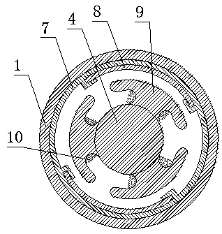
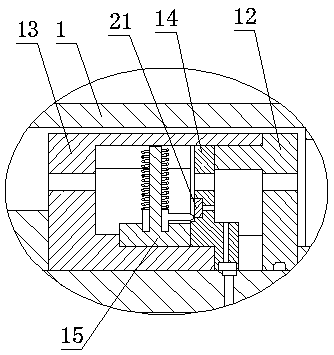
[0026] The electromagnetic speed control pup joint of the downhole tool includes a casing 1, an upper joint 2, a lower joint 3, a rotating shaft 4 and a switch device. The joint 3, the upper righting bearing 5 and the lower righting bearing 6 which are symmetrically arranged in the housing 1 are equipped with a rotating shaft 4, and a plurality of T-shaped pieces 9 are axially evenly distributed on the circumference of the rotating shaft 4, and the T-shaped pieces 9 are wound A coil 10 is formed. On the rotating shaft 4 between the upper righting bearing 5 and the lower righting bearing 6, a magnet 8 is symmetrically installed through a support frame 7, and a lower spline joint 11 is installed on the upper side of the rotating shaft 4 outside the lower righting bearing 6, and the outer side of the upper righting bearing 5 On the rotating shaft 4, a switching device is installed with interference.

[0027] The switch device includes a switch base 12, a guide plate 13, a switch...


PUM


Abstract

The invention relates to a downhole tool electromagnetic rotating speed control pup joint, and belongs to the technical field of oil and natural gas exploitation drilling tools. The downhole tool electromagnetic rotating speed control pup joint comprises a shell, an upper joint, a lower joint, a rotating shaft and a switching device. The rotating shaft is installed in the shell, magnets are symmetrically installed on the rotating shaft through support frames, a lower spline joint is installed on the position, on the outer side of a lower alignment bearing, of the rotating shaft in a threaded mode, the switching device is installed on the position, on the outer side of an upper alignment bearing, of the rotating shaft in an interference mode, and an upper spline joint is installed on the position, on the outer side of the switching device, of the rotating shaft in a threaded mode. According to the downhole tool electromagnetic rotating speed control pup joint, the structure is simple, the design is novel, the problems that an existing speed limiting ring cannot well control the rotating speed of a tool, and once damping grease in the speed limiting ring is used up, the speed limiting ring can lose efficacy, and the speed reducing effect cannot be generated on the tool are solved, the pup joint can meet the requirement of a downhole sand-washing and well-flushing tool for the rotational flow rotating speed so that the tool can reach the best working state under different working conditions, and the downhole tool electromagnetic rotating speed control pup joint has wide application prospects.

Description

technical field [0001] The invention relates to an electromagnetic rotational speed control nipple of downhole tools, which belongs to the technical field of drilling tools for oil and natural gas exploitation. Background technique [0002] After the oil field entered the high water cut period, the sand production of some oil wells became more and more serious, and the sand buried in the oil layer or the sand stuck in the oil pump often occurred. Sandy production fluid has become one of the important problems affecting the stable and increased production of oilfields. [0003] At present, the coiled tubing rotary sand flushing technology is the most basic and widely used method in the drilling field. However, the flow field distribution and working status of the flushing tool will change with the change of the swirling speed. , so that the flushing tool can not play its role well, seriously affecting the effect of downhole sand removal. In order to adjust the swirling spee...

Claims


Application Information

Patent Timeline
IPC IPC(8): E21B21/00E21B17/02
CPCE21B17/02E21B17/028E21B21/00
Inventor 王鹏亢博文冯定
Owner YANGTZE UNIVERSITY
Learn More