Eureka AIR delivers breakthrough ideas for toughest innovation challenges, trusted by R&D personnel around the world.

Direct expansion type evaporator device of complete fresh air unit

A direct-expansion, evaporator technology, used in evaporators/condensers, refrigerators, refrigeration components, etc., can solve problems such as shortening the service life of compressors, and achieve the effect of prolonging the service life and improving the operating environment.

Inactive Publication Date: 2018-02-16
SUZHOU SUJING AIM FAR AIR CONDITIONING
View PDF9 Cites 3 Cited by
  • Summary
  • Abstract
  • Description
  • Claims
  • Application Information

AI Technical Summary

Problems solved by technology

[0003] Under some working conditions, for example, the air intake of the evaporator is all outdoor fresh air, the temperature is very high, and the refrigeration system operates under harsh conditions, which has adverse effects, and finally shortens the service life of the compressor

Method used


Image

  • Direct expansion type evaporator device of complete fresh air unit
  • Direct expansion type evaporator device of complete fresh air unit
  • Direct expansion type evaporator device of complete fresh air unit

Examples


Embodiment 1

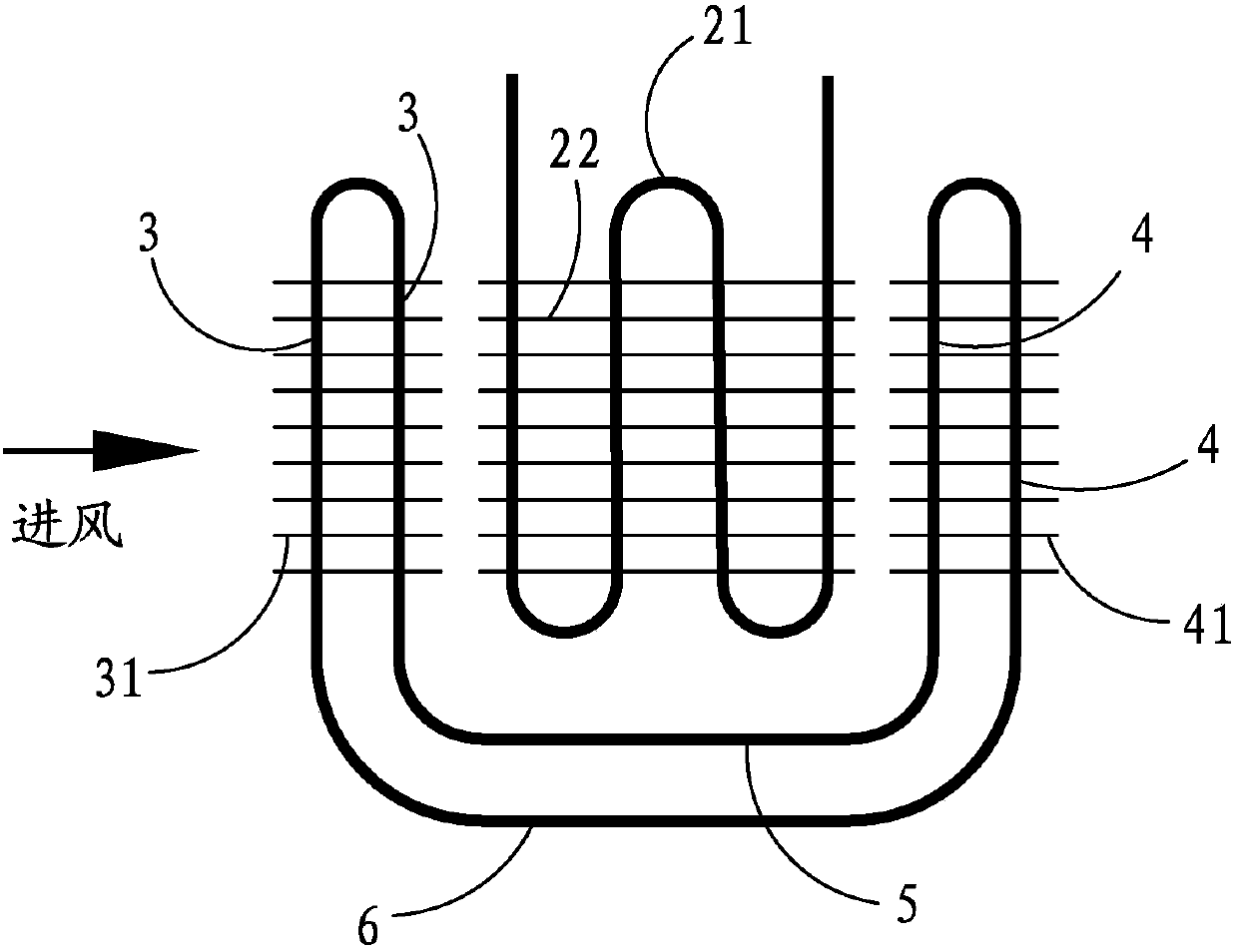
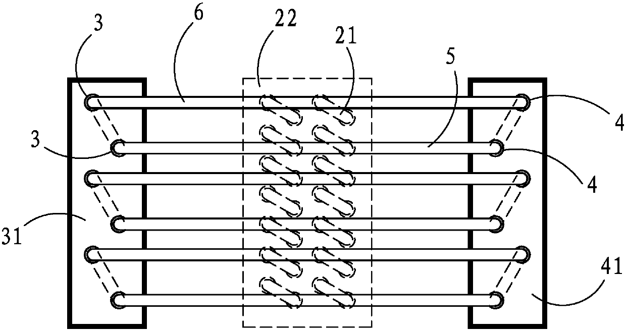
[0023] Embodiment one: see attached figure 1 , 2 , 4, a direct-expansion evaporator device for a fresh air unit, which includes an air duct 1 and a direct-expansion evaporator arranged in the air duct 1, and also includes three heat pipe assemblies, (in other embodiments , any number of heat pipe assemblies can be used) The heat pipe assembly includes an evaporation coil composed of at least two heat pipe evaporator pipes 3, a condensation coil composed of at least two heat pipe condenser pipes 4, and heat pipe steam pipes respectively connected to the evaporation coil and the condensation coil. Pipe 6, and the heat pipe return pipe 5 respectively connected to the evaporating coil and the condensing coil. On the air outlet side of the type evaporator, the evaporating coil, the condensing coil, the heat pipe steam pipe 6 and the heat pipe liquid return pipe 5 form a heat pipe loop and the internal pipes form a closed cavity.

[0024] A working fluid is arranged in the airtigh...

Embodiment 2

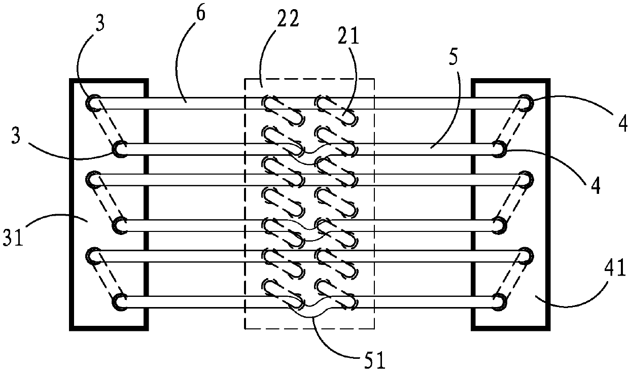
[0032] Embodiment two: see attached figure 1 , 3 , 4, this embodiment is basically the same as Embodiment 1, the difference is that: the heat pipe steam pipe 6 and the heat pipe liquid return pipe 5 are all arranged horizontally, the heat pipe liquid return pipe 5 has a concave curved portion, and the curved portion The height of the upper pipe wall is lower than the height of the lower pipe wall of other parts of the heat pipe liquid return pipe 5 . The bending part is always filled with liquid working medium, which can ensure that all the vaporized working medium in the evaporation coil passes through the steam pipe 6 of the heat pipe and enters the condensation coil.

[0033] Compared with the prior art, the foregoing embodiment has the following advantages:

[0034] 1. In the fresh air air conditioning unit of the above embodiment, the temperature of the airflow entering the direct expansion evaporator is reduced through the heat pipe assembly, which improves the operati...


PUM


Abstract

The invention discloses a direct expansion type evaporator device of a complete fresh air unit. The direct expansion type evaporator device comprises an air flue and a direct expansion type evaporatorand further comprises at least one heat pipe assembly. Each heat pipe assembly comprises an evaporation coil pipe composed of at least two heat pipe evaporation pipes, a condensation coil pipe composed of at least two heat pipe condensation pipes, a heat pipe steam pipe and a heat pipe liquid return pipe, wherein the evaporation coil pipe is arranged in the part, on the air inlet side of the direct expansion type evaporator, in the air flue, the condensation coil pipe is arranged in the part, on the air outlet side of the direct expansion type evaporator, in the air flue, a heat pipe loop isformed by the evaporation coil pipe, the condensation coil pipe, the heat pipe steam pipe and the heat pipe liquid return pipe, and a closed cavity is formed by an inner pipeline. Due to the fact thatin a complete fresh-air air conditioner unit, the temperature of airflow entering the direct expansion type evaporators is reduced through the heat pipe loops of the heat pipe assemblies, the runningenvironment of a steam compression type refrigeration system is improved, and the service life of equipment compressors is prolonged.

Description

technical field [0001] The invention relates to the field of evaporator equipment, in particular to a direct-expansion evaporator device used for cooling an all-new fan unit with relatively high temperature. Background technique [0002] In current production activities, vapor compression refrigeration units are often used, and the refrigerant in the refrigeration unit expands and vaporizes in the evaporator to generate cold energy. In some occasions, the cooling capacity generated by the evaporator is directly used to cool the processed air, which is called a direct expansion cooling refrigerator in the industry, or a direct expansion unit for short. [0003] Under some working conditions, for example, the air intake of the evaporator is all outdoor fresh air, the temperature is very high, and the refrigeration system operates under harsh conditions, which has adverse effects, and finally shortens the service life of the compressor. Contents of the invention [0004] The...

Claims


Application Information

Patent Timeline
Patent Type & Authority Applications(China)
IPC IPC(8): F25B39/02F28D15/02F28F1/30F28F9/013
CPCF25B39/02F28D15/0266F28F1/30F28F9/0131F25B2339/022F25B2500/06
Inventor 庞立升蒋伟尤军
Owner SUZHOU SUJING AIM FAR AIR CONDITIONING
Why Eureka
Eureka Blog
Learn More