

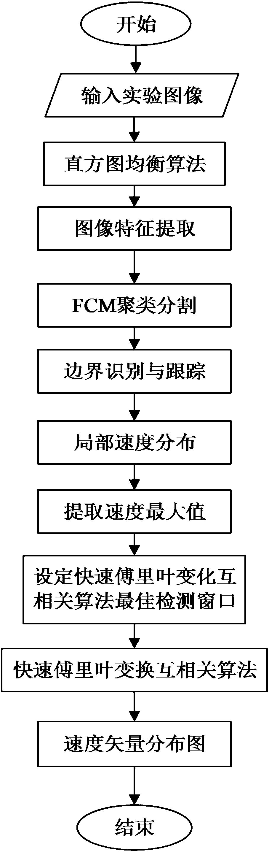
Turbulent boundary layer flow field velocity measurement method based on boundary tracing
A boundary laminar flow and turbulent flow technology, which is applied in fluid velocity measurement, measurement devices, velocity/acceleration/impact measurement, etc., can solve problems such as inability to deal with flow fields, achieve a wide range of applications, improve efficiency, and improve accuracy.
- Summary
- Abstract
- Description
- Claims
- Application Information
AI Technical Summary
Problems solved by technology
Method used
Image

Examples
Embodiment 1
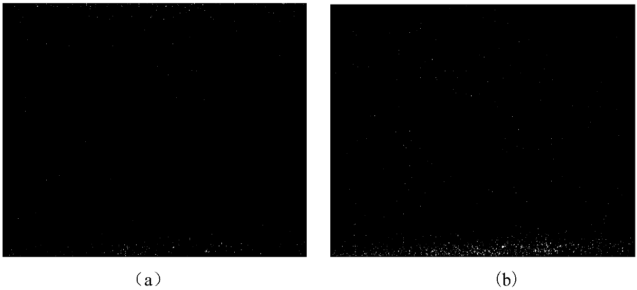
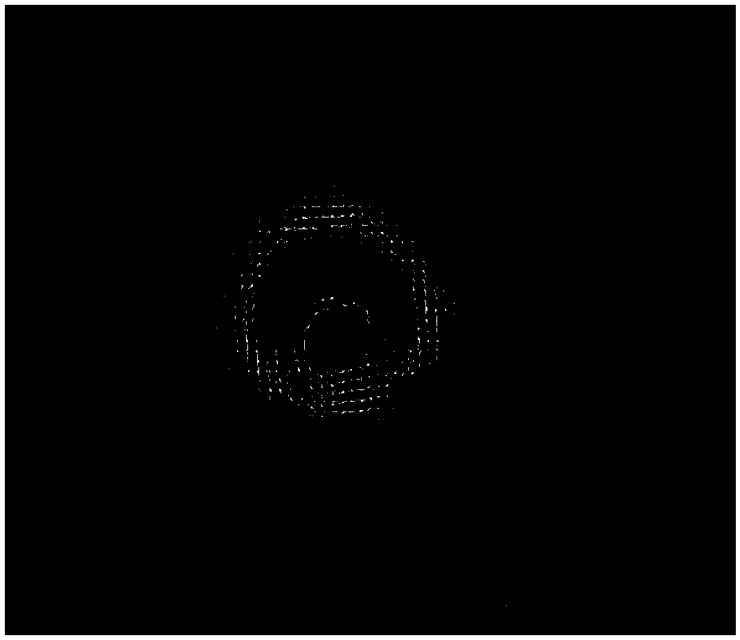
[0064] The image in the double burst process is obtained through experiments, such as Figure 13 shown. And select two images with a very close time interval in the burst process, such as Figure 14 (a) and Figure 14 (b) shown. Process the selected image with an image enhancement program to enhance the image features of hydrogen bubbles, such as Figure 15 (a) and Figure 15 (b) shown. Afterwards, the two images are preprocessed, which includes mean filtering and Gaussian filtering, and then processed by this patent method, and the velocity vector distribution map can be obtained through postprocessing, such as Figure 16 shown. then to Figure 16 By performing velocity extraction, velocity distribution diagrams at different positions can be obtained, such as Figure 17 (a), Figure 17 (b), Figure 17 (c), Figure 17 (d) and Figure 17 (e) shown. The three-burst process is carried out to detect the process, and the velocity distribution at different positions of ...
PUM
 Abstract
Description
Claims
Application Information