Method for generating sub-nanosecond pulse laser

A pulsed laser and sub-nanosecond technology, applied in the laser field, can solve the problems of increased resonant cavity length, difficulty in achieving sub-nanosecond laser output, and difficulty in sub-nanosecond high-energy laser output.

Active Publication Date: 2018-02-16
SHANXI UNIV
View PDF2 Cites 1 Cited by
  • Summary
  • Abstract
  • Description
  • Claims
  • Application Information

AI Technical Summary

Problems solved by technology

Since the length of the resonator is limited by the size of the gain medium and the components in the cavity, it is difficult to achieve sub-nanosecond high-energy laser output under the condition of high repetition rate by using a short resonator length.
Using the method of increasing the transmittance of the output mirror, although the laser pulse width can be narrowed by increasing the pump power, there are problems such as high threshold, easy thermal cracking of the laser crystal, and broadening of the rising edge of the laser pulse.
The method of active and passive double Q-switching needs to introduce additional insertion components, resulting in an increase in the length of the resonant cavity, and it is also difficult to achieve sub-nanosecond laser output

Method used


Image

  • Method for generating sub-nanosecond pulse laser
  • Method for generating sub-nanosecond pulse laser
  • Method for generating sub-nanosecond pulse laser

Examples


Embodiment Construction

[0020] The following will clearly and completely describe the technical solutions in the embodiments of the present invention with reference to the drawings in the embodiments of the present invention. Apparently, the described embodiments are only some of the embodiments of the present invention, but not all of them. Based on the embodiments of the present invention, all other embodiments obtained by persons of ordinary skill in the art without making creative efforts belong to the protection scope of the present invention.

[0021] The purpose of the present invention is to provide a method for generating sub-nanosecond pulsed laser, which is used to shorten the falling edge time of pulsed laser and realize the output of sub-nanosecond pulsed laser under the condition that the conventional resonant cavity is long and no other components are inserted.

[0022] In order to make the above objects, features and advantages of the present invention more comprehensible, the present...


PUM


Abstract

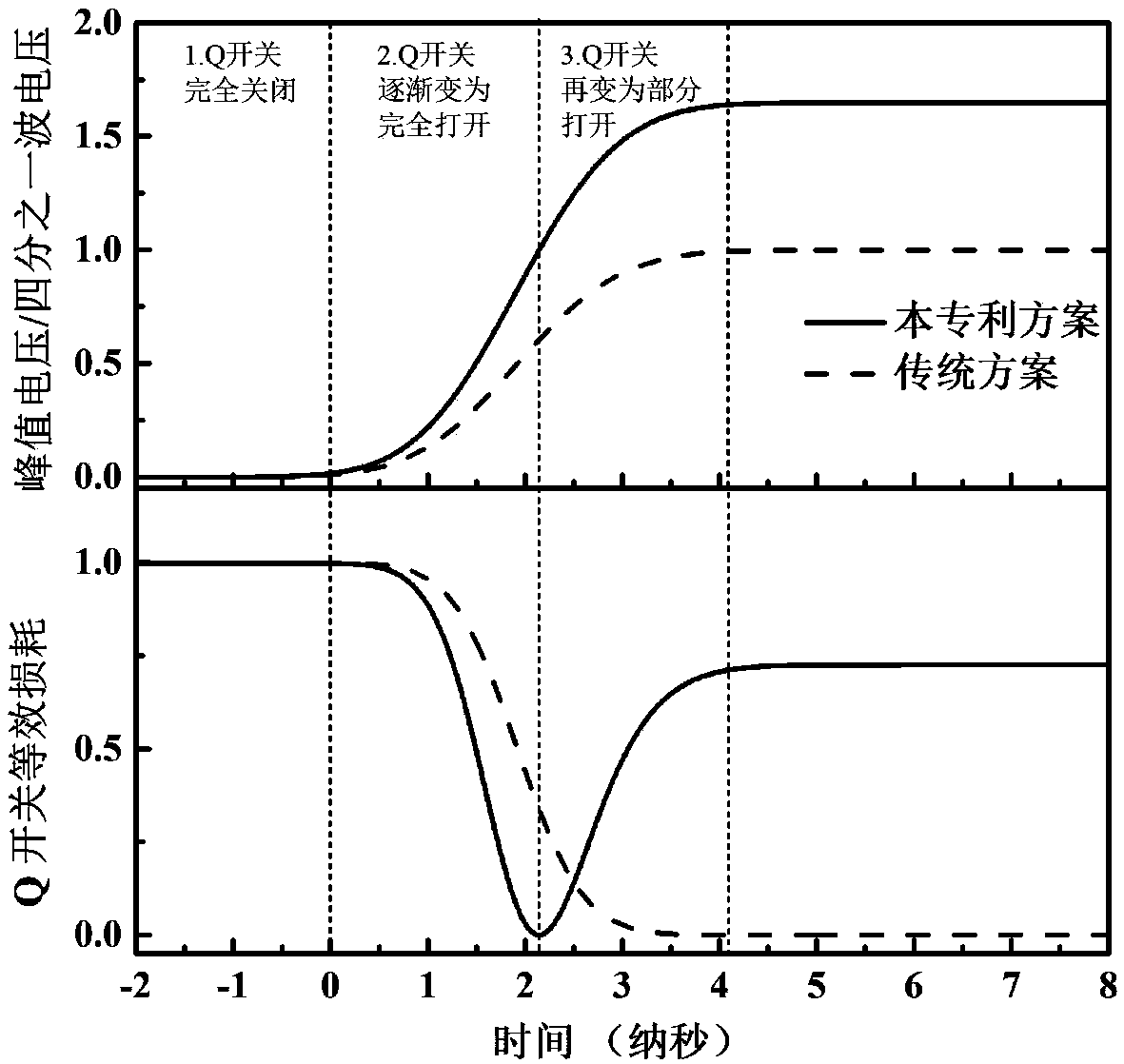
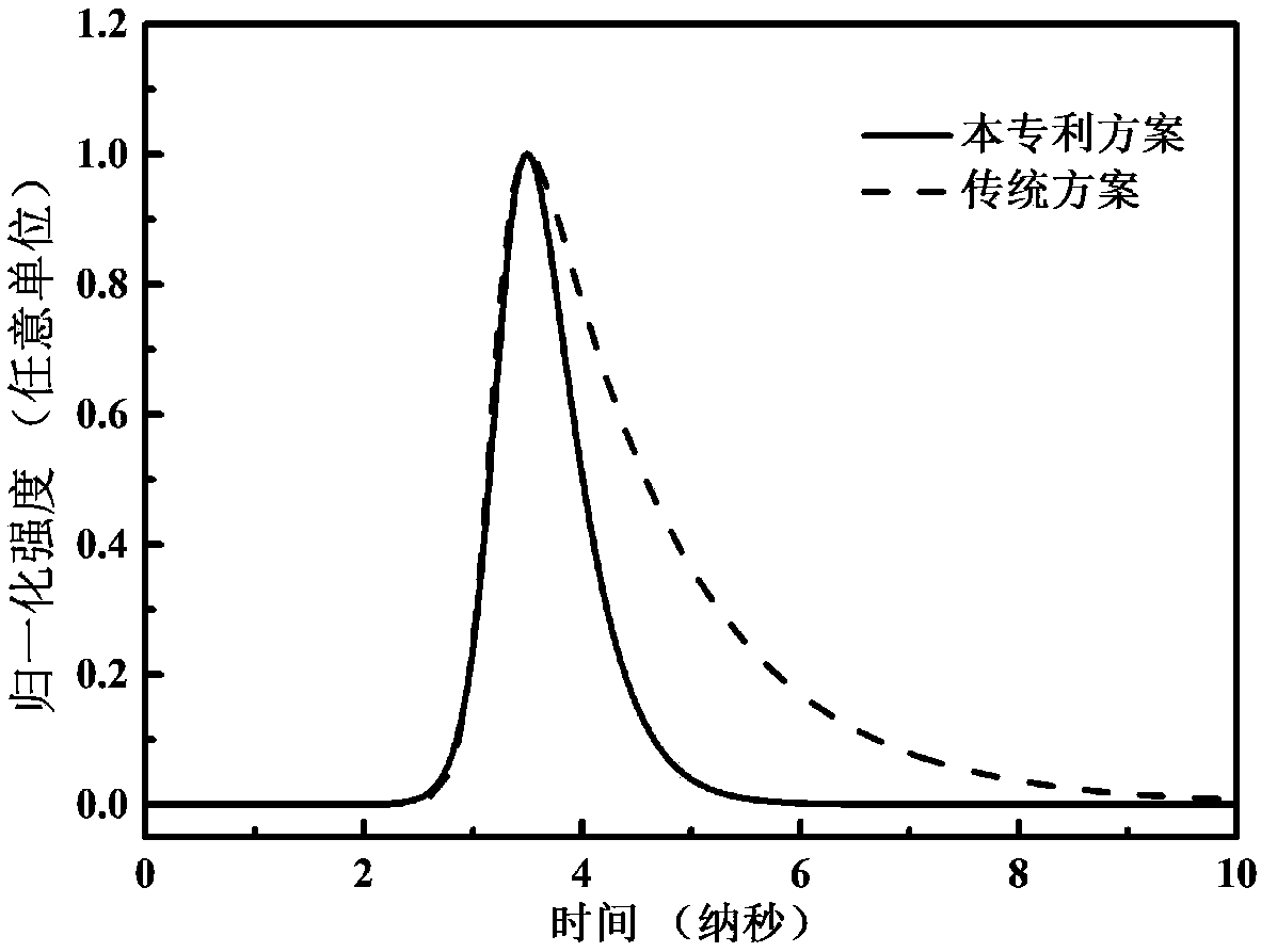
The present invention discloses a method for generating sub-nanosecond pulse laser. The method is applied to a pressurized type electro-optic Q-switched laser. The method includes the following stepsthat: square wave driving signals of which the peak voltage is greater than the voltage of the quarter-waves of a Pockels cell in the in the electro-optic Q-switch are applied to the Pockels cell; during a time when the voltage of the driving signals increased to the peak voltage from 0, the electro-optic Q-switch is converted from a turned-off state to a turned-on state, and then to a partially turned-on state; when the Q-switch is in the turned-off state, a laser gain medium absorbs pump light to achieve the reverse and accumulation of particles; and when the Q-switch is in the partially turned-on state, in-cavity laser vibrates within a resonance cavity in a reciprocating manner, and pulse laser is outputted through an output coupling mirror and a polarizer. The in-cavity vibrating laser is depleted in a very short time, and therefore, the pulse width of the output laser is compressed, and sub-nanosecond pulse laser output is realized.

Description

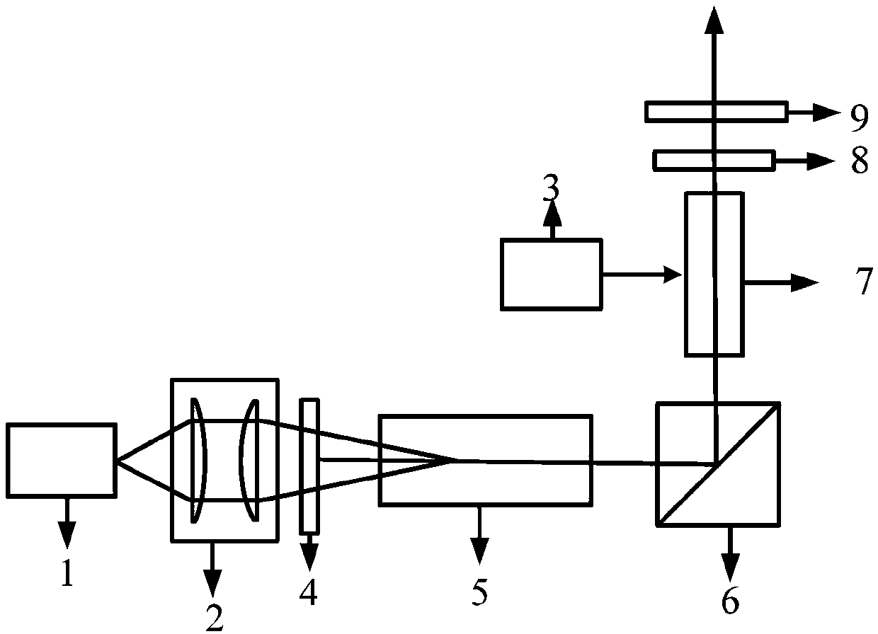
technical field [0001] The invention relates to the field of laser technology, in particular to a method for generating subnanosecond pulsed laser light. Background technique [0002] A pressurized electro-optic Q-switched pulsed laser generally consists of a gain medium 5, an input mirror 4, an output mirror 9, a Pockels cell 7, a quarter-wave plate 8, a polarizer 6, and a pump source 1. The basic structure is as follows: figure 1 shown. The main axis of the quarter-wave plate 8 forms an included angle of 45 degrees with the transmission direction of the polarizer 6, and the Pockels cell 7 and the quarter-wave plate 8 form an electro-optic Q switch and are used to control the polarization direction of the beam in the resonator . When the voltage applied by the electro-optic Q-switch drive source 3 to the Pockels cell in the electro-optic Q-switch is 0, the polarization direction rotation angle of the cavity light beam passing through the Q-switch twice is 90°, and the res...

Claims


Application Information

Patent Timeline
Patent Type & Authority Applications(China)
IPC IPC(8): H01S3/115
CPCH01S3/115H01S3/08054H01S2301/08H01S3/1673H01S3/1611H01S3/09415H01S3/094076H01S3/0815H01S3/0941H01S3/107
Inventor 张宽收赵鑫李渊骥冯晋霞
Owner SHANXI UNIV
Why Eureka
Try Eureka