A photovoltaic charging circuit system

A charging circuit and photovoltaic technology, applied in photovoltaic power generation, battery circuit devices, circuit devices, etc., can solve the problem of lack of drive capability of switch control chips or intelligent control chips, voltage limitations of switch control chips and intelligent control chips, and difficulty in selecting according to actual needs Problems such as switching tubes, to reduce the difficulty of selection, improve compatibility, and improve the effect of driving ability

Active Publication Date: 2021-02-23
FOSHAN SUOER ELECTRONICS IND
View PDF4 Cites 0 Cited by
  • Summary
  • Abstract
  • Description
  • Claims
  • Application Information

AI Technical Summary

Problems solved by technology

[0005] In the traditional technology, in order to reduce the requirement of the output voltage of the charging module, there are multiple rechargeable batteries, and the rechargeable batteries are all of low output voltage, and multiple rechargeable batteries are used in parallel to form a rechargeable battery pack, but at this time, In the inverter module, it is necessary to use the switch tube to convert the DC output of the rechargeable battery pack into AC power, and then boost the voltage through the transformer before it can be used; in the current technology, a switch control chip or an intelligent control chip is commonly used to turn on or off the switch tube switch control, but this control method has its defects, that is, the output voltage of the switch control chip or the intelligent control chip has a certain limit, and it is difficult to drive some switch tubes, that is, the existing switch control chip or intelligent control chip The lack of chip drive capability makes it difficult to select the most suitable switch tube according to actual needs during the design process

Method used


Image

  • A photovoltaic charging circuit system
  • A photovoltaic charging circuit system
  • A photovoltaic charging circuit system

Examples


Embodiment Construction

[0031] The concept, specific structure and technical effects of the present invention will be clearly and completely described below in conjunction with the embodiments and accompanying drawings, so as to fully understand the purpose, features and effects of the present invention. Apparently, the described embodiments are only some of the embodiments of the present invention, rather than all of them. Based on the embodiments of the present invention, other embodiments obtained by those skilled in the art without creative efforts belong to The protection scope of the present invention. In addition, all connection relationships mentioned in the text do not simply refer to the direct connection of components, but mean that a more optimal circuit structure can be formed by adding or reducing connection components according to specific implementation conditions. The various technical features in the invention can be combined interactively on the premise of not conflicting with each...


PUM


Abstract

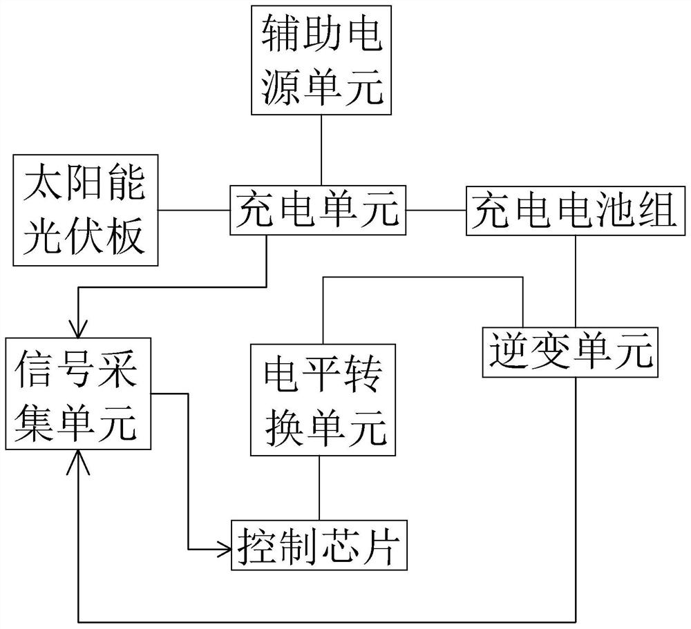
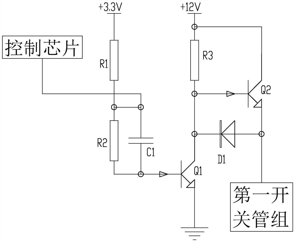
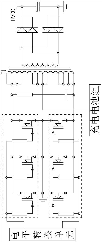
The invention discloses a photovoltaic charging circuit system, which includes a rechargeable battery pack, a solar photovoltaic panel, a charging unit, an inverter unit, a signal acquisition unit, a level conversion unit and a control chip, and the inverter unit includes two first switches tube group, the control chip is connected to the charging unit, the input terminal of the control chip is connected to the output terminal of the signal acquisition unit, and the output terminal of the control chip is respectively connected to the control terminal of the first switching tube group in the inverter unit through the level conversion unit connected. The control chip of the present invention is connected to the control terminal of the first switch tube group in the inverter unit through the level conversion unit, so as to improve the driving ability of the control chip to the first switch tube group, thereby improving the connection between the control chip and various types of switch tubes. Compatibility, reducing the difficulty of switching tube selection in the circuit design process. The invention is used to realize the charging of the rechargeable battery and the output of alternating current by using solar energy.

Description

technical field [0001] The invention relates to an electronic circuit system, more specifically to a photovoltaic charging circuit system applied in the field of solar charging. Background technique [0002] Today in the 21st century, all countries in the world are facing a crisis of energy resources. Conventional resources such as petroleum and coal are decreasing day by day. Therefore, all countries are turning their attention to renewable resources such as wind energy and solar energy. How to efficiently convert renewable energy into electrical energy Or other energy that can be directly utilized has always been a subject of research. [0003] In view of the actual situation of existing renewable energy utilization, the most suitable for promotion and utilization is solar energy. The conventional method of utilizing solar energy is to use the photovoltaic effect to convert light energy into electrical energy, and then charge rechargeable batteries to store electrical ener...

Claims


Application Information

Patent Timeline
Patent Type & Authority Patents(China)
IPC IPC(8): H02J7/35H02J7/00
CPCH02J7/0021H02J7/0013H02J7/35H02J2207/20Y02E10/56
Inventor 刘超祝明建张纪充
Owner FOSHAN SUOER ELECTRONICS IND
Why Eureka
Try Eureka