Ozone flow-field active-molecule distributor

A technology of active molecules and distributors, applied in the field of air pollution control, can solve problems such as inability to achieve deep denitrification, and achieve the effect of uniform injection

Inactive Publication Date: 2018-02-23
江苏天立方环保工程有限公司
View PDF3 Cites 2 Cited by
  • Summary
  • Abstract
  • Description
  • Claims
  • Application Information

AI Technical Summary

Problems solved by technology

[0002] The control of NOx has always been the focus of environmental protection in most countries in the world, and the pollutants it produces are one of the largest pollution sources that cause damage to the ecological environment in our country. Flue gas denitrification Selective catalytic reduction method (SCR for short) Selective non-catalytic reduction method (SNCR for short) Among them, the denitrification principle of the SCR process is to adopt As a reducing agent, it is diluted and sprayed into the inlet flue of the denitrification reactor, and reacts with NOx in the flue gas when passing through the catalyst layer to generate N2 and H2O without secondary pollution and is discharged with the flue gas, while the SNCR process, and the SCR process Compared with As a reducing agent, it is sprayed into the high-temperature zone of the furnace without reducing agent. These two processes have high denitrification efficiency and no secondary pollution. They are widely used in various combustion equipment, but these two processes cannot achieve deep denitrification. Patent CN 205886561 U discloses a kind of ozone flow field injection device, and its main idea is to utilize ozone After partially or fully oxidizing nitrogen monoxide into nitrogen dioxide, nitrogen trioxide or nitrogen pentoxide, use lye to absorb nitrogen oxides and remove nitrogen oxides in flue gas; for ozone denitrification, precise control The flow rate of flue gas and ozone in the flue and how to improve the adequacy of the reaction are part of the core technology of the process

Method used


Image

  • Ozone flow-field active-molecule distributor
  • Ozone flow-field active-molecule distributor
  • Ozone flow-field active-molecule distributor

Examples


Embodiment 1

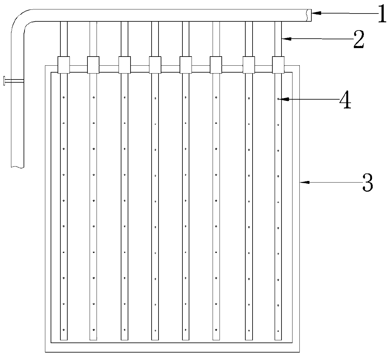
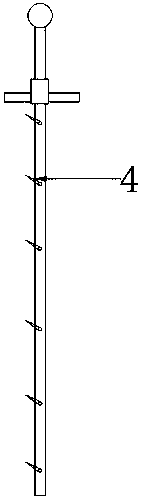
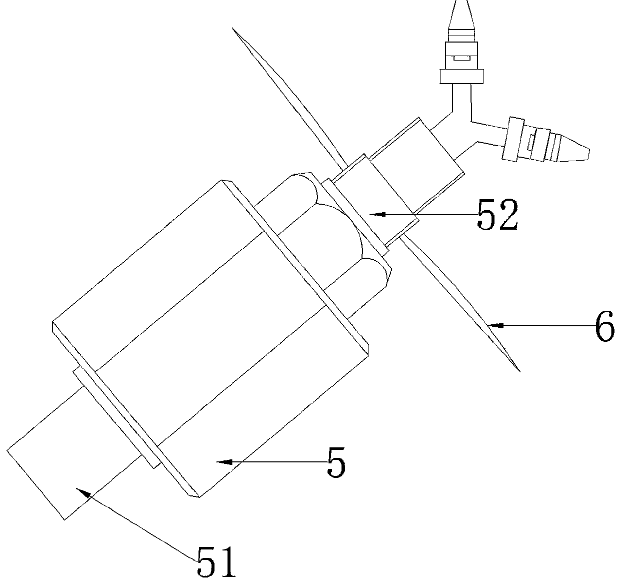
[0021] As shown in the figure, an ozone flow field active molecule distributor includes a main pipe 1, a number of branch pipes 2 connected to the main pipe parallel to each other and arranged at equal intervals, and a number of nozzles 4 arranged on the branch pipes. The branch pipes extend into the smoke Arranged in the channel section 3 and perpendicular to the flue section 3 with a temperature of 50-100°C, the nozzle 4 is connected to the branch pipe 2 through a single-channel rotary joint 5, and the single-channel rotary joint 5 in this embodiment includes a fixed end 51 and a The rotating end 52, wherein, the fixed end 51 is fixedly communicated with the branch pipe 2, and the rotating end 52 is provided with an external thread and an internal thread, and the nozzle 4 is fixed together with the rotating end 52 through the internal thread on the rotating end 52, and the rotating end The outer surface of 52 is screwed with a spoiler mechanism. The spoiler in this embodiment...


PUM


Abstract

The invention provides an ozone flow-field active-molecule distributor, comprising a main pipe, a plurality of parallel and equally spaced branch pipes communicated with the main pipe, and a pluralityof nozzles arranged on the branch pipes, wherein the branch pipes extend into a flue section and are arranged to be perpendicular to the flue section; the nozzles are connected with the branch pipesthrough single-path swivel joints; each of the single-path swivel joints comprises a fixed end and a swivel end; the fixed ends are fixed onto the branch pipes, and the swivel ends are provided with external threads and internal threads; the nozzles are fixed on the swivel ends via the internal threads on the swivel ends; the outer surface of each swivel end is provided with a flow disturbing mechanism; the nozzles are arranged at an equal interval along the direction of the branch pipes; the nozzles on adjacent branch pipes are staggerly arranged; and the nozzles are located on the sides, facing incoming flue gas flow, of the branch pipes. After flue gas is treated by the active-molecule distributor, the efficiency of ozone oxidation of oxynitrides is greatly improved.

Description

technical field [0001] The invention belongs to the field of air pollution control discharged from coal-fired boilers, and in particular relates to an ozone flow field active molecule distributor. Background technique [0002] The control of NOx has always been the focus of environmental protection in most countries in the world, and the pollutants it produces are one of the largest pollution sources that cause damage to the ecological environment in our country. Flue gas denitrification Selective catalytic reduction method (SCR for short) Selective non-catalytic reduction method (SNCR for short) Among them, the denitrification principle of the SCR process is to adopt As a reducing agent, it is diluted and sprayed into the inlet flue of the denitrification reactor, and reacts with NOx in the flue gas when passing through the catalyst layer to generate N2 and H2O without secondary pollution and is discharged with the flue gas, while the SNCR process, and the SCR process Com...

Claims


Application Information

Patent Timeline
Patent Type & Authority Applications(China)
IPC IPC(8): B01D53/76B01D53/56
CPCB01D53/76B01D53/56B01D2251/104B01D2257/404B01D2258/0283
Inventor 李银娣余家鑫
Owner 江苏天立方环保工程有限公司
Why Eureka
Try Eureka