Oil removal treatment device for oily sewage and treatment method

A technology for oil treatment and sewage, which is applied in water/sewage treatment, flotation water/sewage treatment, adsorbed water/sewage treatment, etc. It can solve the problems of not playing an ideal role, difficult to play an ideal effect, and low working efficiency. , to achieve the effect of convenient automatic management, stable treatment effect and low construction cost

Pending Publication Date: 2018-02-23
青岛百利达环保科技有限公司
View PDF6 Cites 4 Cited by
  • Summary
  • Abstract
  • Description
  • Claims
  • Application Information

AI Technical Summary

Problems solved by technology

[0002] Oil refineries and petrochemical enterprises will produce a large amount of oily sewage in the production process, and oil-water separation treatment is required for these oily sewage; the existing oily sewage treatment equipment is mainly divided into two categories: separation of slick oil and separation of emulsified oil. The equipment for floating oil includes tank-in-tank (also known as "oil-water separation and regulating tank"), horizontal oil-water separator, etc., and the equipment for separating emulsified oil includes dissolved air flotation machines and other equipment. The existing above-mentioned equipment is generally separate It is used in work, and the degreasing effect of each equipment is different, and some have higher requirements on the oil content of the incoming water, the scope of application is narrow, and it cannot play an ideal role. The quantity is strictly limited, the work efficiency is low, and it is difficult to achieve the desired effect

Method used


Image

  • Oil removal treatment device for oily sewage and treatment method
  • Oil removal treatment device for oily sewage and treatment method
  • Oil removal treatment device for oily sewage and treatment method

Examples


Embodiment Construction

[0058] The specific implementation manners of the present invention will be further described in detail below in conjunction with the accompanying drawings.

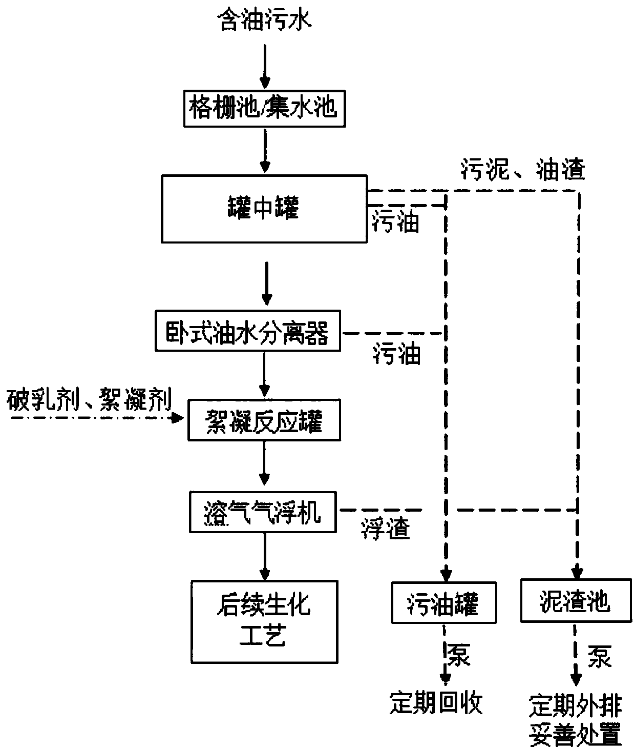
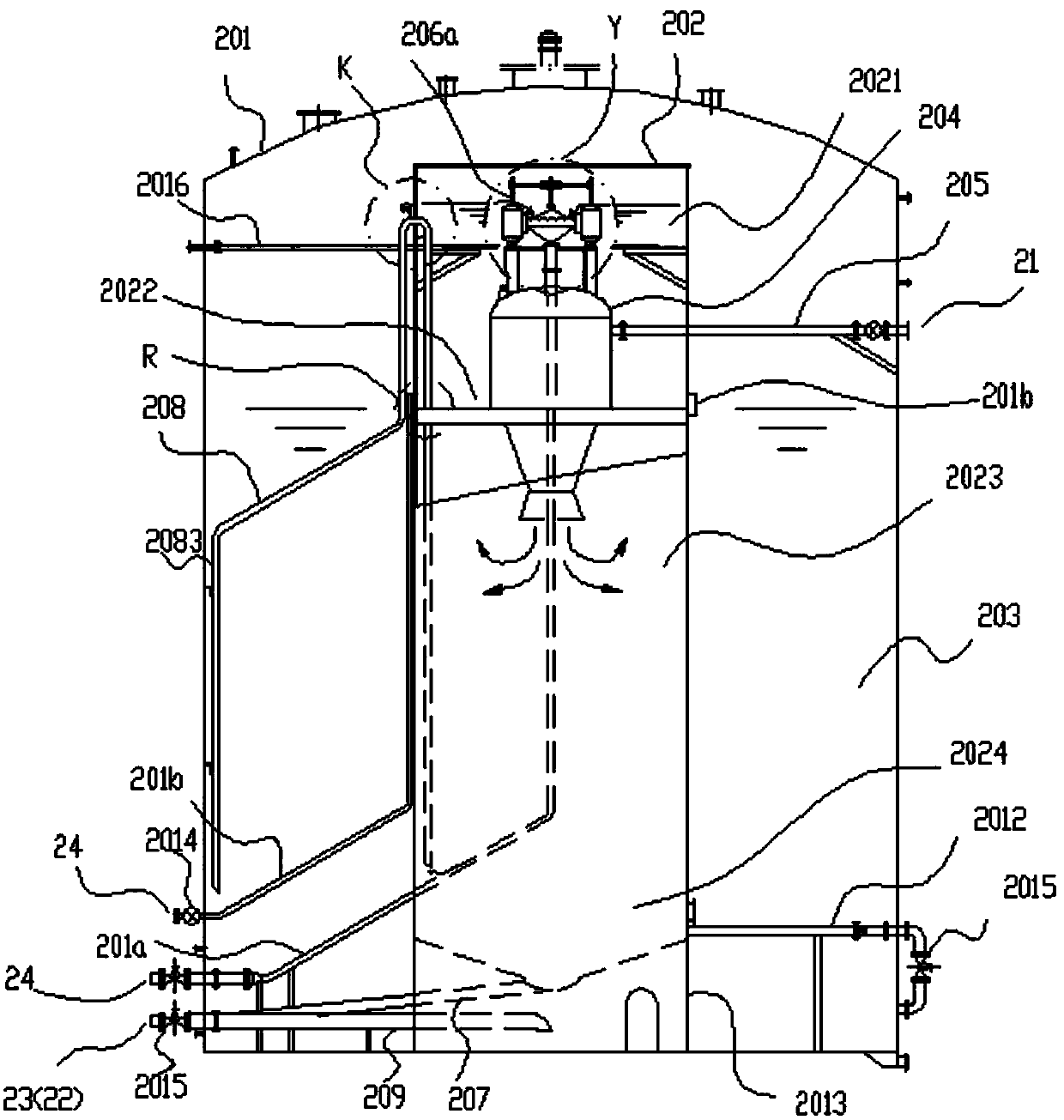
[0059] Such as figure 1 and figure 2 As shown, an oily sewage degreasing treatment device includes a sump 1, a tank in a tank 2, a horizontal oil-water separator 3, a dosing device 7, a flocculation reaction tank 5, a dissolved air flotation machine 6, and a waste oil collection Container 9 and sludge pond 8. The sump 1, the tank-in-tank 2, the horizontal oil-water separator 3, the flocculation reaction tank 5, and the dissolved air flotation machine 6 are sequentially connected, and the oily sewage to be treated is first collected in the sump 1, and then passes through the tank in turn. Tank 2, horizontal oil-water separator 3, flocculation reaction tank 5, dissolved air flotation machine 6 are discharged after treatment.

[0060] Preferably, a grid pool 4 is also provided on the front side of the sump pool 1, and a...


PUM


Abstract

The invention relates to an oil removal treatment device for oily sewage. The oil removal treatment device for the oily sewage comprises a water collecting tank, a tank within a tank, a horizontal type oil-water separator, a chemical feeding device, a flocculation reaction tank, a dissolved air flotation machine, a dirty oil collecting container and a sludge tank, wherein the water collecting tank, the tank within the tank, the horizontal type oil-water separator, the flocculation reaction tank and the dissolved air flotation machine are sequentially connected, to-be-treated oily sewage is firstly collected into the water collecting tank, then is treated by the tank within the tank, the horizontal type oil-water separator, the flocculation reaction tank and the dissolved air flotation machine sequentially and then is discharged. The invention also relates to a sewage treatment method utilizing the oil removal treatment device for the oily sewage, oil content of the sewage treated by the oil removal treatment device is less than or equal to 20mg / l, and requirement of oil in effluent for later-period advanced treatment can be met. The oil removal treatment device provided by the invention is wide in application range and high in treatment efficiency.

Description

technical field [0001] The invention relates to the field of sewage treatment, in particular to an oily sewage degreasing treatment device and treatment method. Background technique [0002] Oil refineries and petrochemical enterprises will produce a large amount of oily sewage in the production process, and oil-water separation treatment is required for these oily sewage; the existing oily sewage treatment equipment is mainly divided into two categories: separation of slick oil and separation of emulsified oil. The equipment for floating oil includes tank-in-tank (also known as "oil-water separation and regulating tank"), horizontal oil-water separator, etc., and the equipment for separating emulsified oil includes dissolved air flotation machines and other equipment. The existing above-mentioned equipment is generally separate It is used in work, and the degreasing effect of each equipment is different, and some have higher requirements on the oil content of the incoming w...

Claims


Application Information

Patent Timeline
Patent Type & Authority Applications(China)
IPC IPC(8): C02F9/04C02F1/40C02F101/32
CPCC02F1/40C02F9/00C02F2201/007C02F2101/32C02F2301/08C02F1/001C02F1/38C02F1/28C02F1/24C02F1/52
Inventor 王晶晶
Owner 青岛百利达环保科技有限公司
Why Eureka
Try Eureka