Hydraulic supply device for engine

A hydraulic supply and supply device technology, applied in the field of hydraulic pumps, can solve the problems of high cost, inaccurate pressure sensor detection results, complex structure, etc., and achieve the effect of simple structure, convenient and accurate control

Pending Publication Date: 2018-02-23
DONGFENG MOTOR CORP HUBEI
View PDF5 Cites 6 Cited by
  • Summary
  • Abstract
  • Description
  • Claims
  • Application Information

AI Technical Summary

Problems solved by technology

This kind of device has high cost and complex structure, and the pressure sensor will change its properties over time, so it needs to be adjusted frequently to maintain accuracy. When it cannot be adjusted in time, the detection result of the pressure sensor will be inaccurate, which will cause the output oil pressure. not stable enough

Method used


Image

  • Hydraulic supply device for engine
  • Hydraulic supply device for engine

Examples


Embodiment Construction

[0025] In the following description, numerous specific details are set forth in order to provide a thorough understanding of the application. However, the present application can be implemented in many other ways that are different from those described here, and those skilled in the art can make similar promotions without violating the connotation of the present application, so the present application is not limited by the specific implementation disclosed below.

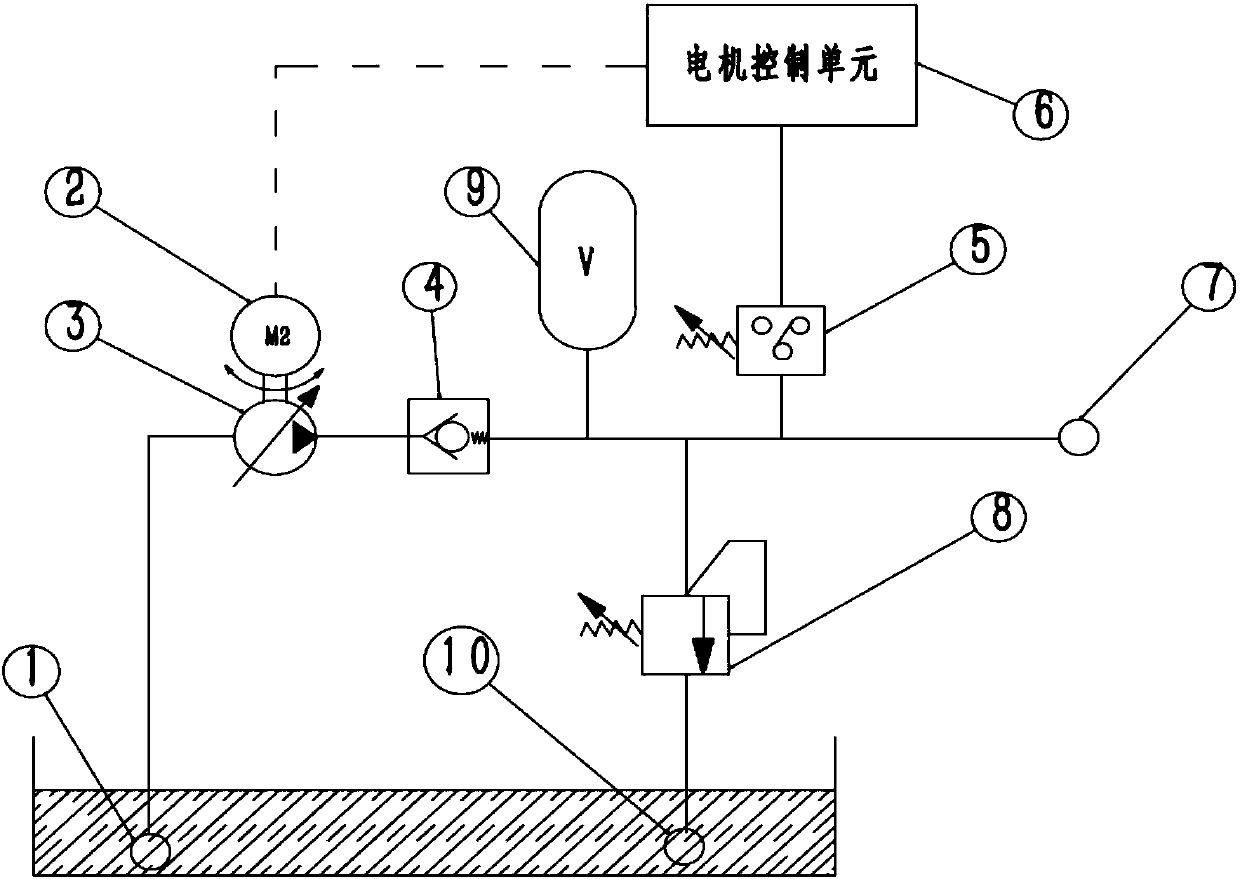
[0026] The present invention provides an engine hydraulic supply device, the following combination figure 1 , figure 2 An engine hydraulic supply device provided by an embodiment of the present invention will be described in detail.

[0027] like figure 1 As shown in FIG. 1 , a schematic structural view of an engine hydraulic supply device provided by the first embodiment of the present invention is shown. Among them, 1. Inlet, 2. Electric motor, 3. Oil pump, 4. Check valve, 5. Single point pressure detection un...


PUM


Abstract

The invention discloses a hydraulic supply device for an engine. The supply device is used for providing driving force. When the outlet pressure is lower than the set control pressure, a single-pointpressure detection unit is in the first state; a motor is driven to work by controlling a motor control unit, and furthermore, an oil pump is driven to operate, so that engine oil flows therein through an inlet and flows out of an outlet; and the outlet pressure is increased. When the outlet pressure is equal to or greater than the set control pressure, the single-point pressure detection unit isin the second state; and at the moment, a delay control module on the motor control unit continues to drive the motor to work for a delayed period of time and then stop according to the set delaying duration, so that the outlet pressure is increased continuously. By adjusting the delaying duration, the outlet pressure can be precisely controlled within the required pressure range. By means of thehydraulic supply device for the engine, on the premise that the structure which is simple to the greatest extent and low-cost elements are adopted, hydraulic output of the pressure within the specified range is provided outwards stably; and in addition, the hydraulic supply device does not need calibration basically and is convenient and precise to control.

Description

technical field [0001] The invention relates to the technical field of hydraulic pumps, in particular to an engine hydraulic supply device. Background technique [0002] In a supercharged engine, the compression ratio is lower than in a naturally aspirated engine in order to prevent knocking. Thermal efficiency decreases at low boost pressures, reducing fuel economy. In order to solve this problem, it is an important method to adopt variable compression ratio engine. [0003] The variable compression ratio engine includes a high compression ratio working mode and a low compression ratio working mode. When the engine is working under low load conditions with low supercharging pressure, make the engine work in the high compression ratio working mode, so that the compression ratio can be increased to the same or higher than that of the naturally aspirated engine to improve thermal efficiency; when the engine is working at high Under the supercharged high load condition, make...

Claims


Application Information

Patent Timeline
Patent Type & Authority Applications(China)
IPC IPC(8): F04B17/03F04B49/06F15B1/02
CPCF04B17/03F04B49/06F15B1/02F15B2211/212F15B2211/205
Inventor 李耀军张群坡钟贤兵胡全兵邓冰
Owner DONGFENG MOTOR CORP HUBEI
Why Eureka
Try Eureka