
Grating Wavefront Tilt Dispersion Compensation Device

A dispersion compensation and wavefront tilting technology, applied in the field of ultra-short and ultra-intense lasers, can solve problems such as hundreds of femtoseconds in length, and achieve the effects of eliminating influence, reliable solutions, and reducing system errors

Active Publication Date: 2019-06-21
SHANGHAI INST OF OPTICS & FINE MECHANICS CHINESE ACAD OF SCI
View PDF4 Cites 0 Cited by
  • Summary
  • Abstract
  • Description
  • Claims
  • Application Information

AI Technical Summary

Problems solved by technology

When using the single autocorrelation method to measure laser pulses, if two beams of ultrashort pulses are directly used to generate autocorrelation signals in the crystal, due to many conditions such as the aperture of the optical element, the size of the crystal, and the flux of the sampled laser, it is only possible to achieve the best results. Long measuring range of hundreds of femtoseconds

Method used


Image

  • Grating Wavefront Tilt Dispersion Compensation Device
  • Grating Wavefront Tilt Dispersion Compensation Device
  • Grating Wavefront Tilt Dispersion Compensation Device

Examples


Embodiment 1

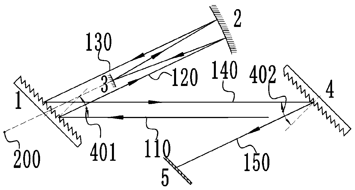
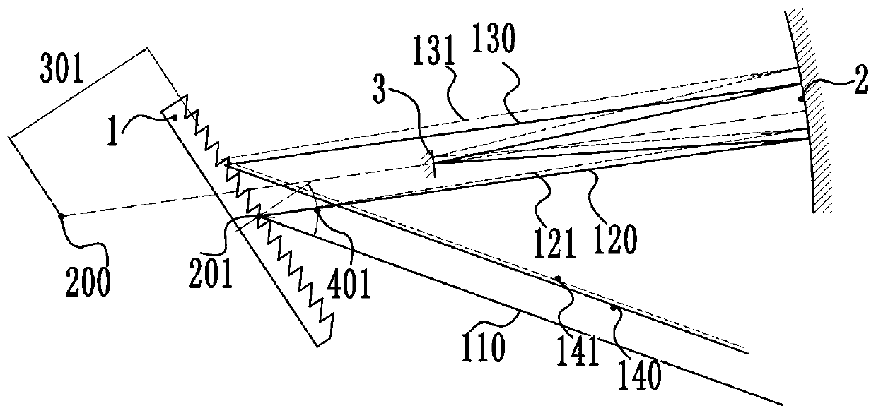
[0017] figure 1 It is a schematic structural diagram of Embodiment 1 of the grating wavefront tilt dispersion compensation device of the present invention, with figure 1 , image 3 and Figure 4 The application method of the present invention in wave front tilt acquisition technology is described. It can be seen from the figure that the grating wavefront tilt dispersion compensation device of the present invention includes a first blazed grating 1, an Offner optical system and a second blazed grating 4, the Offner optical system is composed of a concave reflector 2 and a convex reflector 3, the first The grating constant of the second blazed grating 4 is equal to the grating constant of the first blazed grating 1, the radius of curvature of the concave reflector 2 is twice the radius of curvature of the convex reflector 3, and the concave reflector The center of curvature of 2 and the center of curvature of the convex mirror 3 coincide at a point 200; after the incident lig...

Embodiment 2

[0038] The difference between embodiment 2 and embodiment 1 is that both the concave reflector and the convex reflector are cylindrical reflectors.

Embodiment 3

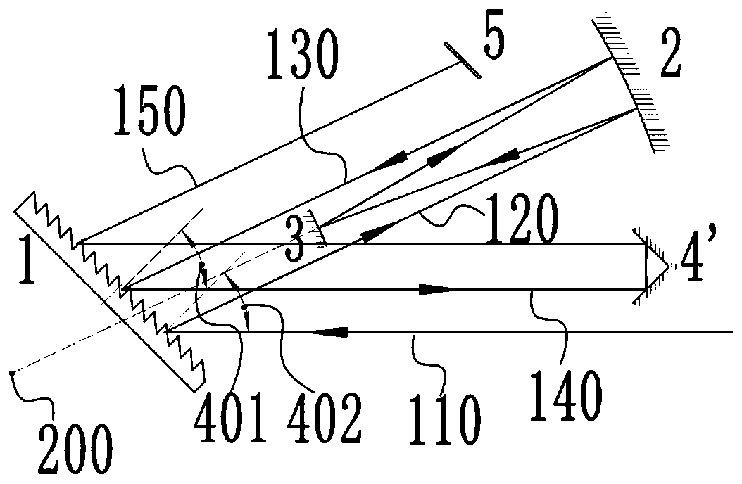
[0040] see figure 2 , figure 2 It is a schematic diagram of the structural light path of Embodiment 3 of the grating wavefront tilt dispersion compensation device of the present invention. It can be seen from the figure that the grating wavefront tilt dispersion compensation device of the present invention includes a first blazed grating 1, an Offner optical system and a right-angle mirror 4'. Described Offner optical system is made of concave reflector 2 and convex reflector 3, and the radius of curvature of described concave reflector 2 is 2 times of the radius of curvature of described convex reflector 3, and described concave reflector 2 It coincides with the center of curvature of the convex reflector 3 at a point 200; after the incident light 110 is diffracted by the first blazed grating 1, the first diffracted light 120 output by the first blazed grating 1 is incident on the concave reflector 2. After being reflected by the concave reflector 2 for the first time, it ...


PUM


Abstract

A grating wavefront inclined dispersion compensation device, comprising a first blazed grating, an Offner optical system and a second blazed grating or a right-angle reflector. The grating wavefront inclined dispersion compensation device compensates for temporal stretching and spatial stretching caused by a grating angular dispersion effect, and ensures that the time-space dispersion of a light beam is zero when the light beam reaches a working surface. Compared to conventional grating-based wavefront inclination acquisition technology, the present invention fundamentally eliminates the influence of the grating angular dispersion effect on the applied effect of wavefront inclination technology.

Description

technical field [0001] The invention relates to an ultra-short and ultra-intense laser, in particular to a grating wavefront tilt dispersion compensation device, which uses a grating single autocorrelation method to measure the pulse when measuring the ultra-short pulse time characteristics with a pulse width greater than 100 femtoseconds. Background technique [0002] In the field of ultra-short and ultra-intense laser technology, laser pulse width and pulse signal-to-noise ratio are extremely important parameters for evaluating its output performance. Ultrashort pulse measurement has two methods: direct measurement and indirect measurement. The direct measurement scheme adopts the method of fast response photodetector + high-speed oscilloscope or measurement with streak camera. Indirect measurement schemes include scanning (or single) second-order (or third-order) correlation method, frequency-resolved optical switch method, self-referencing spectral phase coherent electri...

Claims


Application Information

Patent Timeline
Patent Type & Authority Patents(China)
IPC IPC(8): G01J11/00G02B27/42G02B27/44
CPCG01J11/00G02B27/4233G02B27/44
Inventor 唐顺兴朱宝强
Owner SHANGHAI INST OF OPTICS & FINE MECHANICS CHINESE ACAD OF SCI
Learn More