
A Passive Radar System with Multiple Antenna Array Switching

A passive radar and multi-antenna technology, which is applied in the field of civil aviation, can solve the problems affecting the system's clutter suppression ability and low-altitude and slow-speed target detection ability, and the increase of system cost, so as to achieve the effect of reducing the total system cost and improving system performance

Active Publication Date: 2021-11-05
芜湖华创光电科技有限公司
View PDF14 Cites 0 Cited by
  • Summary
  • Abstract
  • Description
  • Claims
  • Application Information

AI Technical Summary

Problems solved by technology

Radar systems usually used for target surveillance in civil aviation need to achieve 360° coverage in the azimuth direction. In order to achieve 360° azimuth airspace coverage, passive radar systems often use circular array antennas, but circular array antennas The sidelobe of the azimuth pattern is usually high, so it will affect the system's clutter suppression ability and low-altitude and slow-moving target detection ability
If it is necessary to obtain lower sidelobes, it is necessary to increase the number of element antennas in the array antenna. Due to the adoption of the digital array antenna system, the increase in the number of antennas will lead to a linear increase in system costs

Method used


Image

  • A Passive Radar System with Multiple Antenna Array Switching
  • A Passive Radar System with Multiple Antenna Array Switching
  • A Passive Radar System with Multiple Antenna Array Switching

Examples


Embodiment Construction

[0027] The idea, specific structure and technical effects of the present invention will be further described below in conjunction with the accompanying drawings, so as to fully understand the purpose, features and effects of the present invention.

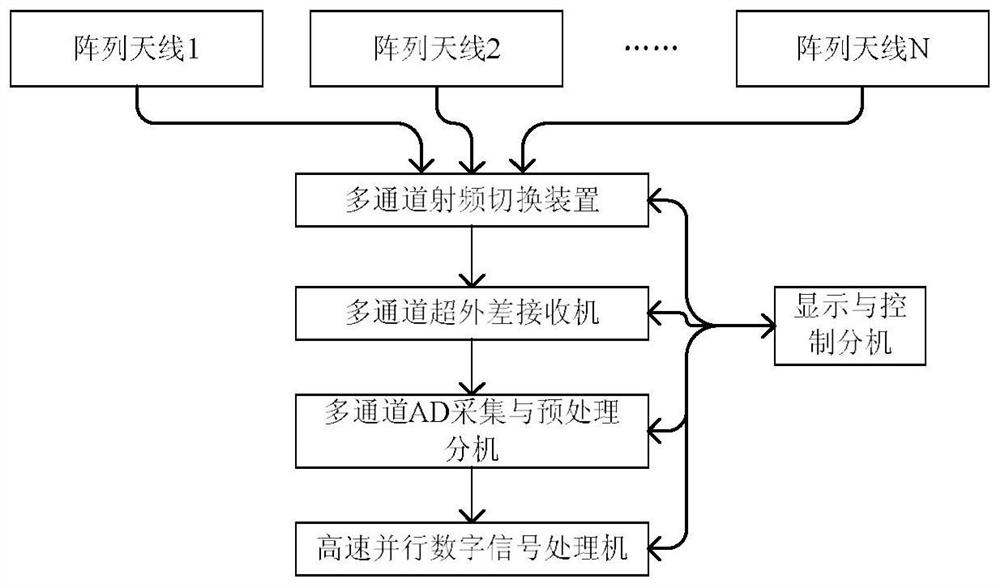
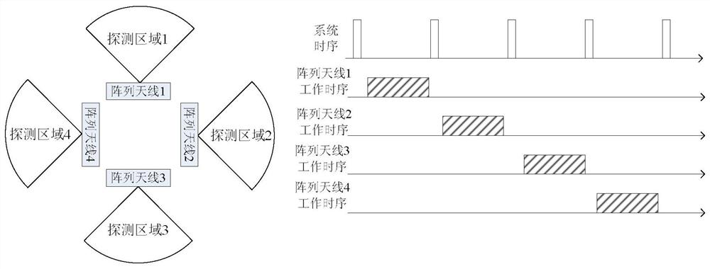
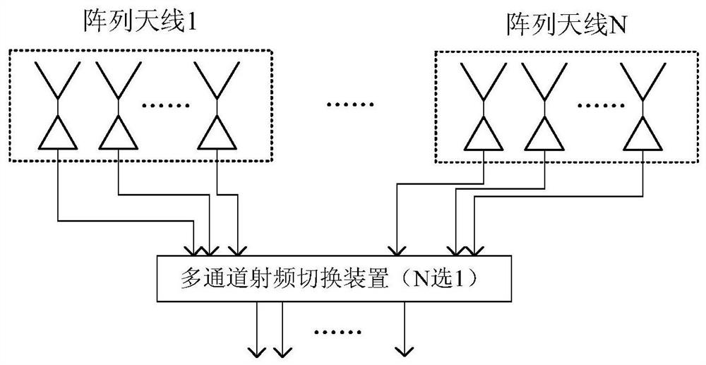
[0028] The composition of the multi-array antenna switching passive radar system proposed by the present invention is as follows: figure 1 shown. The system is mainly composed of several array antennas, multi-channel radio frequency switching devices, multi-channel superheterodyne receivers, multi-channel AD acquisition and preprocessing extensions, high-speed parallel digital signal processors, and display and control extensions. When the system is working, the multi-channel radio frequency switching device selects one of the array antennas within a fixed time period according to a certain timing, and sends the signal received by the array antenna to the multi-channel superheterodyne receiver, which is received by the multi-channe...


PUM


Abstract

The invention discloses a passive radar system with multi-antenna array switching. The system includes a plurality of array antennas and jointly covers azimuth 360° air space. The multi-channel radio frequency switching device gates one of the array antennas within a fixed time period according to the timing, sends the signal received by the array antenna to the multi-channel superheterodyne receiver, converts the multi-channel radio frequency signals to a fixed intermediate frequency, and then converts the intermediate frequency signal Send it to the multi-channel AD acquisition and preprocessing extension to complete the AD acquisition and digital down-conversion of the intermediate frequency analog signal, and then hand it over to the high-speed parallel digital signal processing extension to complete clutter suppression, target detection, positioning and tracking. The system switches between multiple antenna arrays in turn according to a certain time sequence, realizing the 360° airspace coverage of the passive radar. Compared with the traditional circular array array antenna, the antenna sidelobe is lower, the clutter suppression ability is strong, and the low-altitude target detection ability At the same time, the cost of the system can be effectively controlled.

Description

technical field [0001] The invention relates to the technical field of civil aviation, in particular to the composition structure of a passive radar system for monitoring air targets by utilizing external radiation source irradiation. Background technique [0002] The passive radar system that uses civil radio and television stations as the irradiation source to receive the echo signal reflected by the air target and realizes the positioning and tracking of the target has the advantages of low cost, strong low-altitude detection capability, no electromagnetic pollution and good electromagnetic compatibility. It is widely used in civil aviation. The application prospect of the field is very broad. [0003] Existing passive radar systems usually use digital array antennas and digital beamforming technology, and a single array antenna can cover a wide range of airspace instantaneously. Radar systems usually used for target surveillance in civil aviation need to achieve 360° co...

Claims


Application Information

Patent Timeline
Patent Type & Authority Patents(China)
IPC IPC(8): G01S13/06G01S13/66
CPCG01S13/06G01S13/66
Inventor 吴双
Owner 芜湖华创光电科技有限公司
Learn More