Manufacturing method and production equipment for alignment film
A technology of production equipment and manufacturing method, applied in the optical field, can solve the problems of low product yield, electrostatic damage to the orientation film, low efficiency, etc., and achieve the effects of improved production efficiency, good reliability consistency, stable and consistent performance
- Summary
- Abstract
- Description
- Claims
- Application Information
AI Technical Summary
Problems solved by technology
Method used
Image


Examples
Embodiment 1
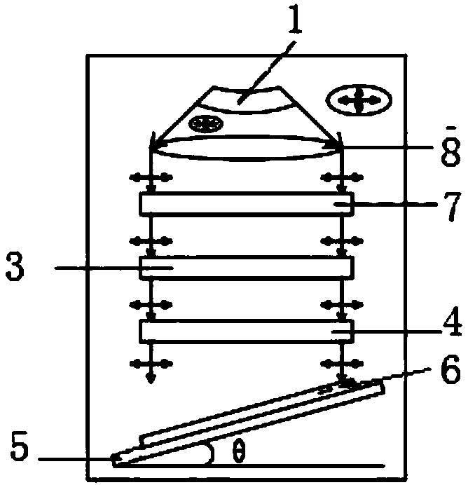
[0027] Embodiment 1: The UV light source 1 is incident vertically downward through the parallel mirror 2, the parallel lens 2 is used to convert the point light source into a parallel beam, and the UV light source 1 is arranged obliquely below the parallel mirror 2, The included angle between the substrate platform 5 and the horizontal plane is 30° to 60°, so that the light source is far away from the reflector and the energy transmission is not high. The light source in the UVB band, the working light of the UV light source illuminates the parallel mirror 2 upwards, and the parallel mirror 2 reflects the scattered light out of the parallel beam. At this time, the beam is still unpolarized natural light, and the beam is incident on the wire grid Plate 3, through the polarizing action of the polarizing plate, emits a UVB light beam with a polarized state from the polarizing plate, passes through the protective plate 4, forms a certain angle with the substrate coated with the ori...
Embodiment 2
[0028] Embodiment 2: as image 3 As shown, the UV light source 1 passes through a parallel lens 8, and the parallel lens 8 is used to convert a point light source into a parallel beam. The UV light source 1 is arranged above the parallel lens 8, so that the light source is closer to the lens. The transmission amount is high, so a quartz insulating glass 7 is arranged between the parallel lens 8 and the wire grid polarizing plate 3 . Since the light intensity of this structure is relatively large and generates a lot of heat, it is necessary to filter the light beam through the quartz heat-insulating glass 7 to filter out the heat-generating wavelength. To the wire grid polarizing plate 3, through the polarization of the polarizing plate, a UVB light beam with a polarization state is emitted from the polarizing plate, passes through the protective plate 4, forms a certain angle with the substrate coated with the orientation film, and aligns the orientation film For exposure, th...
Embodiment 3
[0030] Embodiment 3: as Figure 4 As shown, the included angle between the substrate platform 5 and the horizontal plane is 0°, and a reflective mirror 9 is also included between the protection 4 and the substrate platform 5 . The working light of the UV light source shines upwards on the parallel light reflector, and the parallel light reflector 2 reflects the scattered light out of the parallel light beam. At this time, the light beam is still unpolarized natural state light, and the light beam is incident on the wire grid polarizing plate 3 again. The polarizing effect of the polarizing plate emits a UVB beam with a polarization state from the polarizing plate, passes through the protective plate 4, and shines on the mirror 9, and the light is reflected to the substrate coated with an orientation film, and the incident light forms a certain angle with the substrate , to perform alignment exposure on the alignment film, and turn off the UVB light source after reaching the se...
PUM
| Property | Measurement | Unit |
|---|---|---|
| angle | aaaaa | aaaaa |
Abstract
Description
Claims
Application Information