Electric automobile brake power-assisted vacuum pump controller circuit and control method

A technology for assisting vacuum pumps and electric vehicles. It is applied in the fields of automatic control, pressure sensors, and amplifier circuits. It can solve the problems of low safety and reliability, inability to detect the working status of vacuum pumps, frequent startup or non-stop of vacuum pumps, etc., and achieve reliable safety performance.

Pending Publication Date: 2018-02-23
TIANJIN ZHONGHUAN SANFENG ELECTRONICS
View PDF0 Cites 3 Cited by
  • Summary
  • Abstract
  • Description
  • Claims
  • Application Information

AI Technical Summary

Problems solved by technology

At present, domestic vacuum pump controllers are relatively simple in technology and low in safety and reliability. During use, there are problems such as non-stop and non-start, power input terminals are subjected to voltage shocks, and components are burned. In a cruel environment, the start point and stop point deviate from the design. The fixed value will cause the vacuum pump to start frequently or not stop, which greatly consumes the service life of the vacuum pump and the battery, and is easy to cause damage to the vacuum pump.
[0003] For example, the products on the market use an electric pressure switch to start the vacuum pump for 8 seconds when it is lower than the set value, and then stop working. The working characteristics are very mechanical and the control accuracy is low. In the environment, not only the sensitivity is low, but also it is very easy to malfunction, and the safety stability is very low

Method used


Image

  • Electric automobile brake power-assisted vacuum pump controller circuit and control method
  • Electric automobile brake power-assisted vacuum pump controller circuit and control method
  • Electric automobile brake power-assisted vacuum pump controller circuit and control method

Examples


Embodiment Construction

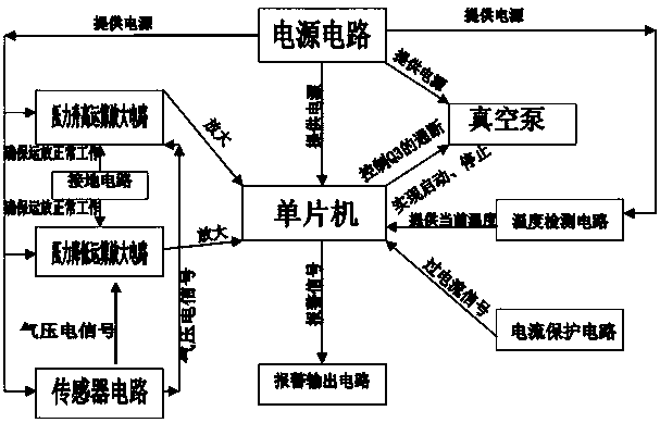
[0034] Such as Figure 1 to Figure 10 As shown, a brake booster vacuum pump controller circuit for an electric vehicle includes a vacuum pump, a vacuum pump controller, and a vacuum tank. The vacuum pump controller is connected to the vacuum pump, the vacuum pump is connected to the vacuum tank, and the vacuum pump controller is embedded in the vacuum tank.

[0035] The vacuum pump controller circuit includes a single-chip microcomputer, a power supply circuit, a pressure increase operation amplifier circuit, a pressure decrease operation amplifier circuit, a grounding circuit, a sensor circuit, an alarm output circuit, a temperature detection circuit, and a current protection circuit.

[0036] The single-chip microcomputer is respectively connected with the pressure increase operational amplifier circuit, the pressure decrease operational amplifier circuit, the grounding circuit, the sensor circuit, the alarm output circuit, the temperature detection circuit, the current prote...


PUM


Abstract

The invention relates to a brake booster vacuum pump controller circuit and a control method for an electric vehicle. The pressure increase operation amplifier circuit and the pressure decrease operation amplifier circuit respectively provide amplified signals to the single-chip microcomputer, the alarm output circuit provides the alarm signal to the single-chip computer, and the temperature detection circuit supplies the single-chip microcomputer. Provide the current temperature signal, the current protection circuit provides an overcurrent signal to the single-chip microcomputer, the single-chip microcomputer controls the start of the vacuum pump, the sensor circuit provides the pneumatic signal, the grounding circuit ensures the normal operation of the two operational amplifier circuits, and the power supply circuit increases the pressure. Reduce the operational amplifier circuit, ground circuit, sensor circuit, single chip microcomputer, temperature detection circuit and vacuum pump to provide power. The invention realizes the control of the air pressure value in the vacuum tank by controlling the start and stop of the vacuum pump, and plays the role of brake booster. The invention has multiple protection functions, avoids burning out the vacuum pump, and improves the service life of the vacuum pump and the storage battery.

Description

technical field [0001] The invention provides a brake booster vacuum pump controller circuit and control method for an electric vehicle, which relates to the fields of pressure sensors, automatic control, amplification circuits, etc., and controls the negative air pressure in the vacuum tank to play the role of brake booster. Background technique [0002] New energy vehicles are one of the strategic emerging industries that China is accelerating its cultivation and development, and its market share is increasing year by year. New energy vehicles have become a trend and can enjoy various favorable policies. At present, domestic vacuum pump controllers are relatively simple in technology and low in safety and reliability. During use, there are problems such as non-stop and non-start, power input terminals are subjected to voltage shocks, and components are burned. In a cruel environment, the start point and stop point deviate from the design. If the value is fixed, the vacuum ...

Claims


Application Information

Patent Timeline
Patent Type & Authority Applications(China)
IPC IPC(8): G05B19/042
CPCG05B19/0423G05B2219/24215
Inventor 田启孟王双存张军曹跃付长海刘伟
Owner TIANJIN ZHONGHUAN SANFENG ELECTRONICS
Why Eureka
Try Eureka