Infrared thermal imaging system-based fault recognition method

A technology of infrared thermal imaging and fault identification, which is applied in character and pattern recognition, radiation pyrometry, optical radiation measurement, etc., can solve the problems of inability to detect synthetic electrical equipment, low accuracy and efficiency, and high labor intensity. Achieve the effects of fast speed, high accuracy and labor saving

Inactive Publication Date: 2018-02-23
NANJING UNIV OF SCI & TECH
View PDF2 Cites 26 Cited by
  • Summary
  • Abstract
  • Description
  • Claims
  • Application Information

AI Technical Summary

Problems solved by technology

Although these testing methods are simple, their accuracy and efficiency are low, not only labor-intensive, but also po

Method used


Image

  • Infrared thermal imaging system-based fault recognition method
  • Infrared thermal imaging system-based fault recognition method
  • Infrared thermal imaging system-based fault recognition method

Examples


Embodiment 1

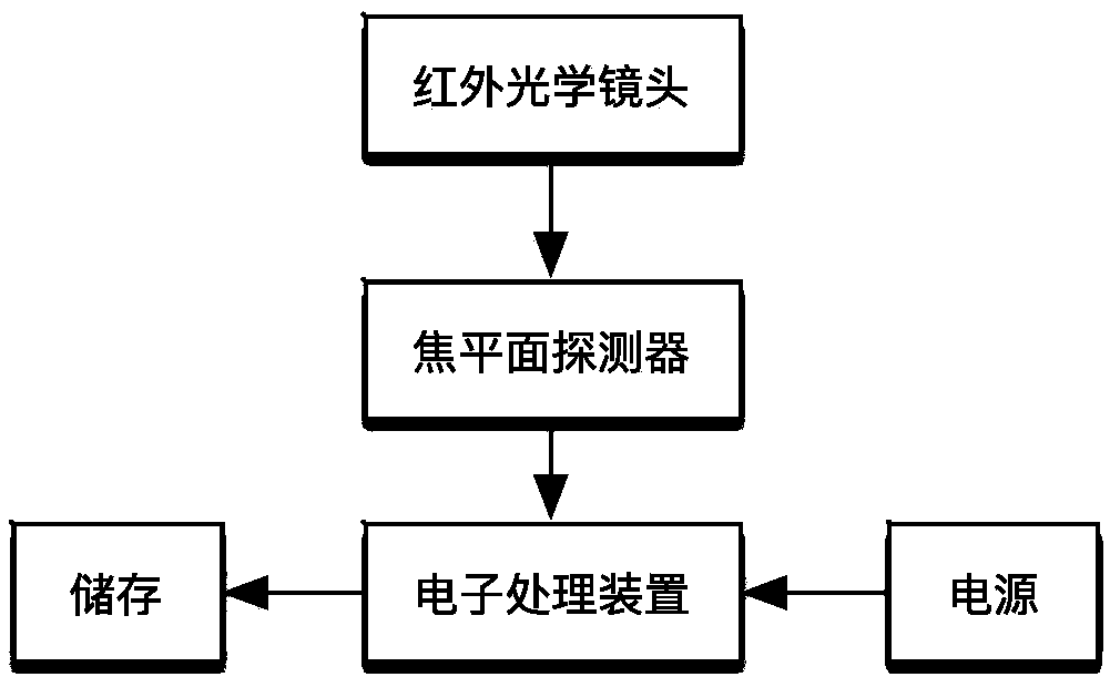
[0085] figure 1 This embodiment provides a structural diagram of an infrared thermal imaging instrument. The infrared thermal imager used in the embodiment of the present invention obtains an imaging image, including an infrared optical lens, a focal plane detector, and an electronic processing device connected in sequence. The electronic processing The devices are respectively connected with a power supply and a storage device, and the measurement principle of the infrared thermal imager is as follows: the infrared thermal imager technology is a non-contact diagnostic technology for scanning and imaging the thermal radiation of an object. The infrared thermal image of an object actually corresponds to the two-dimensional temperature field on its surface. According to Stephen Boltzmann's law, the relationship between the absolute temperature of the object surface and the infrared radiation power of the object is determined. The radiation energy level of the measured object is i...


PUM


Abstract

The invention discloses an infrared thermal imaging system-based fault recognition method. The method comprises the following steps of: 1, shooting electric equipment by adoption of an infrared thermal imaging system so as to obtain an infrared image of the electric equipment, and preprocessing the infrared image of the electric equipment; 2, carrying out threshold value segmentation on the preprocessed infrared image by adoption of a maximum entropy method; 3, carrying out edge detection on the infrared image after the threshold value segmentation by taking a Prewitt operator as an edge detection operator; 4, carrying out expansion processing on the infrared image after the edge detection by using an expansion algorithm; and 5, fusing the infrared image of the electric equipment after theexpansion processing with a visible image of original electric equipment so as to differentiate heating targets in the electric equipment from surrounding background. According to the method, an infrared temperature image processing technology is utilized to search temperature heating abnormal points and automatically judge operation condition and fault information of the electric equipment, so that the operation condition of the electric equipment is online and rapidly detected.

Description

Technical field [0001] The invention relates to the technical field of designing electrical equipment monitoring, in particular to a fault identification method based on an infrared thermal imaging system. Background technique [0002] With the expansion of the scale of the power grid and the improvement of the level of automation, the task of equipment maintenance and repair has become heavier and more expensive. At present, power supply companies basically use spark gap discharge forks and short-circuit forks to manually climb the poles to detect the operating conditions of electrical equipment. Although these test methods are simple, their accuracy and efficiency are low. They are not only labor-intensive and poor in safety, but also cannot be tested for synthetic electrical equipment that is almost always used on a large scale. Summary of the invention [0003] The purpose of the present invention is to provide a fast and accurate fault identification method based on an infra...

Claims


Application Information

Patent Timeline
IPC IPC(8): G06K9/54G06K9/32G01J5/00
CPCG01J5/0096G01J2005/0077G06V10/25G06V10/20
Inventor 黄成徐鹏陈嘉金威李炳炳徐志良王力立
Owner NANJING UNIV OF SCI & TECH
Why Eureka
Try Eureka