Filtering antenna based on slot line resonator

A filtering antenna and resonator technology, which is applied in the direction of antenna, antenna grounding device, antenna grounding switch structure connection, etc., can solve the problems of limited bandwidth of filtering antenna, complex antenna structure, complex structure, etc., and achieve the advantages of structural processing difficulty Effect

Active Publication Date: 2018-02-23
NANJING UNIV OF SCI & TECH
View PDF3 Cites 3 Cited by
  • Summary
  • Abstract
  • Description
  • Claims
  • Application Information

AI Technical Summary

Problems solved by technology

[0003] In 2014, Xiu Yin Zhang, Wen Duan and Yong-Mei Pan published "High-Gain Filtering Patch Antenna Without Extra Circuit" in E.Y.Jung and H.Y.Hwang on IEEE Transaction on Antennas and Propagation, and proposed to use a double-layer dielectric board to design a filter antenna , and by adding a short-circuit column and a U-shaped slot to introduce a zero point to improve the rectangular coefficient of the passband, the final design of the filter antenna has a relative bandwidth of 16%, but the structure is complex and the production cost is high
[0004] In 2016, GuangHua Sun and SaiWai Wong published "A Compact Printed Filtering Antenna With GoodSuppression of Upper Harmonic Band" on IEEE Antennas and Wireless Propagation Letters, proposing to use stepped impedance dipoles, stepped impedance resonators and low-pass filters to realize the filtering antenna design, the bandwidth is increased to 27.5%, but the structure of the antenna is complex, and it is difficult to process in practical applications
[0005] To sum up, the existing filter antennas have limited bandwidth and complex structures

Method used


Image

  • Filtering antenna based on slot line resonator
  • Filtering antenna based on slot line resonator
  • Filtering antenna based on slot line resonator

Examples


Embodiment 1

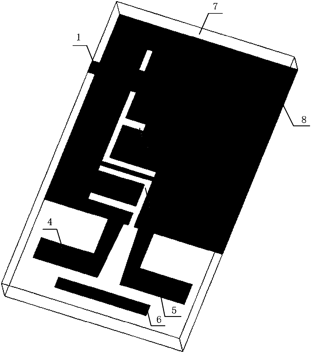
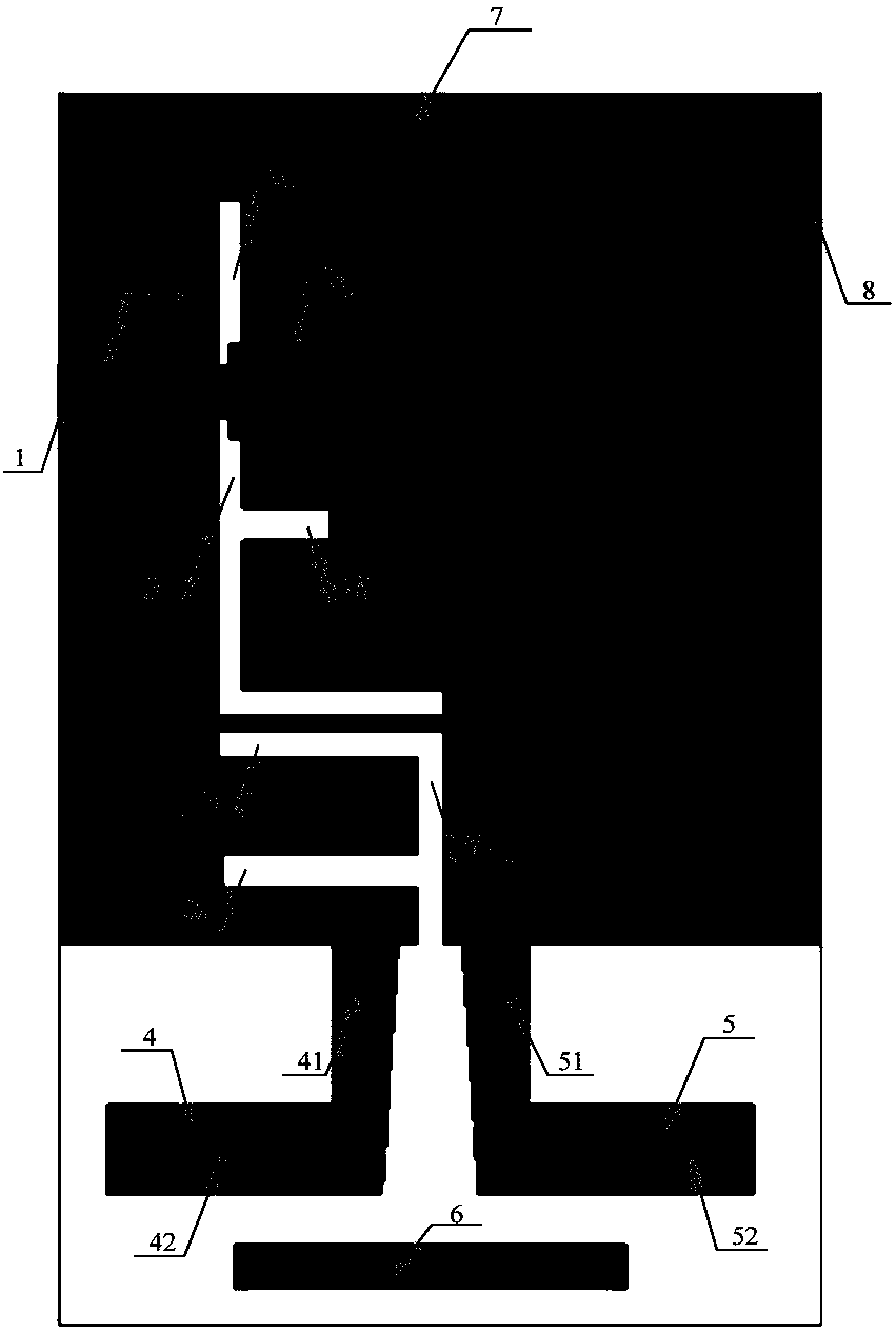
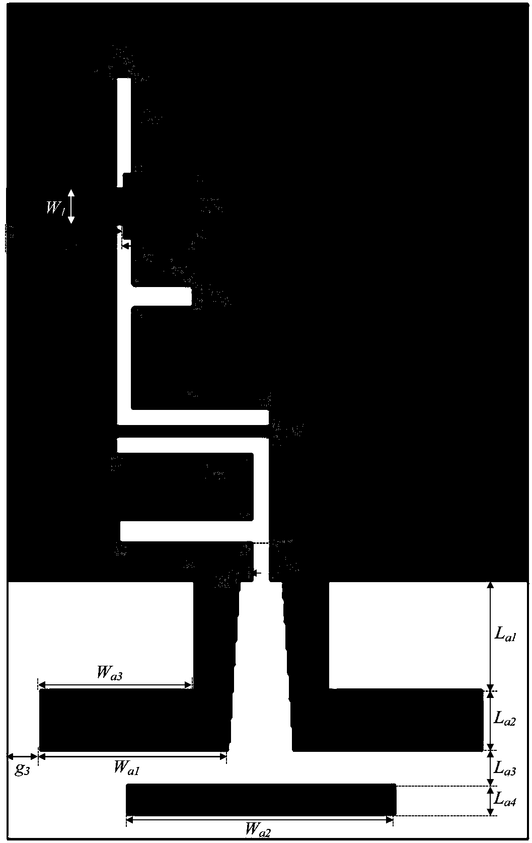
[0052]The three-dimensional structure of a new type of ultra-wideband balun filter is as follows: figure 1 As shown, the top view is as figure 2 As shown, the relevant dimensions and specifications are as follows image 3 shown. The dielectric substrate 7 used has a relative permittivity of 2.2, a thickness of 0.508 mm, and a loss tangent of 0.0009. combine image 3 , the various sizes of the filter antenna in this embodiment are as follows: W1=1.6mm, W2=2.9, Ws1=0.1mm, Ws2=0.6mm, g1=0.3mm, g2=0.1mm, g3=0.7mm, Wa1=10.8 mm, Wa2=12mm, Wa3=9mm, Ls1=3.35mm, L1=4.95mm, L2=3.2mm, Ls2=3.4mm, Ls3=11.6mm, Ls4=10.8mm, Ls5=6.7mm, Ls6=2.1mm, La1=9mm, La2=2.8mm, La3=1.5mm, La4=1.4mm. The overall area of ​​the ultra-wideband balun filter is 42mm×23.6mm, and the corresponding guide wavelength size is 1.2λ g ×0.67λ g , where λ g is the guided wavelength corresponding to the center frequency of the passband.

[0053] The UWB filter antenna in this example is modeled and simulated in ...


PUM


Abstract

The invention discloses a filtering antenna based on a slot line resonator. The filtering antenna comprises a rectangular dielectric substrate (7), a metal grounding plate (8) and an input port feeder(1), wherein an F-shaped slot line resonator (2) and a slot line transmission line (3) are etched in the metal grounding plate (8), a vertical arm (21) of the F-shaped slot line resonator (2) is parallel to a long side of the dielectric substrate (7), and a vertical arm (31) of the slot line transmission line (3) is parallel to the long side of the dielectric substrate (7); the input port feeder(1) is positioned above the F-shaped slot line resonator (2) and is perpendicular to the long side of the dielectric substrate (7), and an input end of the input port feeder (1) is positioned on a long side of the of the dielectric substrate (7); and the filtering antenna further comprises a first antenna radiating unit (4), a second antenna radiating unit (5) and an antenna directing unit (6). The filtering antenna based on the slot line resonator has the advantages of wide bandwidth and simple structure.

Description

technical field [0001] The invention relates to the technical field of microwave passive devices, in particular to a slot-line resonator-based filter antenna with wide bandwidth and simple structure. Background technique [0002] As a new wireless communication technology, UWB wireless technology has attracted the attention of many scholars in recent years. Antenna and filter are the two most important components of the RF front-end circuit. Their size and performance determine the quality of the entire communication system. The traditional design method focuses on the design of the device itself. After the two are cascaded in the system, they cannot guarantee a complete match. And the size of the circuit is too large. In this design, the filter and the antenna are designed as a filter antenna as a whole, which can reduce the size of the circuit and have both filtering and radiation effects; Research has increasingly become the focus of scholars' research. [0003] In 2014...

Claims


Application Information

Patent Timeline
Patent Type & Authority Applications(China)
IPC IPC(8): H01Q1/48H01Q1/38H01Q1/50H01Q19/02
CPCH01Q1/38H01Q1/48H01Q1/50H01Q19/02
Inventor 徐艳卉王雪道徐海艳王建朋
Owner NANJING UNIV OF SCI & TECH
Why Eureka
Try Eureka