

Compound braking system with brake-by-wire function
A brake-by-wire and compound brake technology, which is applied in the direction of brake transmission, brake, transportation and packaging, etc., can solve the problems of low control precision, safety of brake failure, rapid change of oil pressure, etc., to ensure vehicle control The effects of dynamic safety, adjustment accuracy improvement, and hydraulic change slowdown
- Summary
- Abstract
- Description
- Claims
- Application Information
AI Technical Summary
Problems solved by technology
Method used
Image

Examples
Embodiment Construction
[0022] The present invention will be further described in detail below in conjunction with the accompanying drawings and specific embodiments.
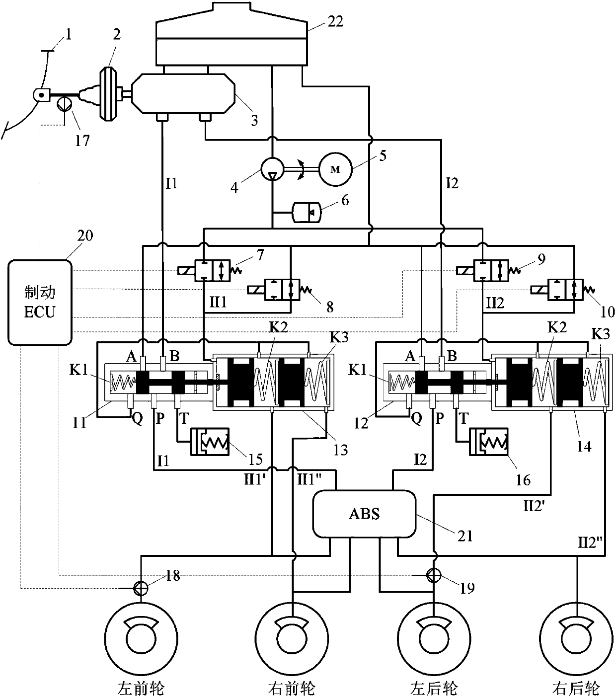
[0023] like figure 1 Shown is a compound brake system with brake-by-wire function, which includes brake pedal 1, brake booster 2, brake master cylinder 3, two-position five-way slide valve a11, two-position five-way slide valve b12, Stroke simulator a15, stroke simulator b16, hydraulic adjustment module (motor 5, oil pump, high pressure accumulator 6, 2-position 2-way solenoid valve a7, 2-position 2-way solenoid valve b8, 2-position 2-way solenoid valve c9, 2-position 2-way solenoid valve Two-way solenoid valve d10, hydraulic adjustment cylinder a13, hydraulic adjustment cylinder b14), pedal displacement sensor 17, pressure sensor a18, pressure sensor b19 and brake controller 20.
[0024] The structure integrates two brake hydraulic control systems. One is a traditional brake system that generates hydraulic pressure through a mecha...
PUM
 Abstract
Description
Claims
Application Information