Method for weaving 2.5D angle-interlock preformed part with section gradually decreasing

A prefabricated, corner interlocking technology, used in textiles, papermaking, fabrics, textiles, etc., can solve the problems of increased processes, inability to complete, and reduced performance of parts, to improve quality and performance, reduce fiber damage, and reduce processing. The effect of the process

Inactive Publication Date: 2018-02-27
TIANJIN POLYTECHNIC UNIV
0 Cites 1 Cited by

AI-Extracted Technical Summary

Problems solved by technology

For the overall preforming of such variable cross-section parts, the traditional basic three-dimensional weaving method or technology cannot be completed, and cannot meet the requirements of high-performance composite materials for preforms
The current solution is to use traditional machining methods to obtain the required variable-section shape on the basis of the corresponding equal-section preformed parts, such ...

Method used

The advantage of the braiding method of the present invention is to apply yarn reduction and thinning operation skillfully and scientifically, so that the cross-sectional change of the composite material special-shaped preform can be formed by the integral weaving of reinforcing fibers, thus reducing the mechanical The fiber damage caused by proces...

Abstract

The invention relates to a method for weaving a 2.5D angle-interlock preformed part with the section gradually decreasing. On the basis of a layer-layer angle-interlock weaving process, the method ischaracterized in that in the weaving process, with one end surface of the preformed part as a standard, according to the change of the size of the section of the preformed part and the movement law ofyarn, the quantity and positions of yarn-reducing points in a plane in the weaving direction are designed, and the yarn-reducing points are evenly distributed; by means of the methods of yarn reduction, yarn movement and yarn reed replacement, the section change of the preformed part is achieved, and the section-variable preformed part is woven. The method is simple and high in applicability, thewoven formed part is good in integrity, and the mechanical properties of composites can be improved.

Application Domain

Technology Topic

Image

  • Method for weaving 2.5D angle-interlock preformed part with section gradually decreasing
  • Method for weaving 2.5D angle-interlock preformed part with section gradually decreasing
  • Method for weaving 2.5D angle-interlock preformed part with section gradually decreasing

Examples

  • Experimental program(1)

Example Embodiment

[0028] Example 1:
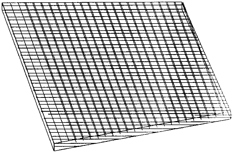
[0029] Adopt the trapezoidal body component (referring to of the inventive method weaving) Image 6 ). The cross-sectional size of its large end is 100mm×1.5mm (width×thickness), the trapezoid height is 100mm, the warp yarn density is 10 yarns/cm, the weft yarn density is 8 yarns/cm, the warp and weft yarns are carbon fiber T300-3K, and the reed used is 10 teeth/cm. According to the size requirements and density of the workpiece, the number of warp yarns required is 500, and the length of the warp yarns must be at least greater than 100mm.
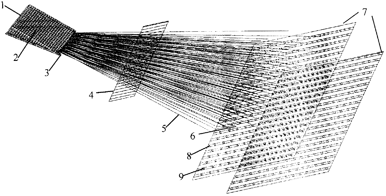
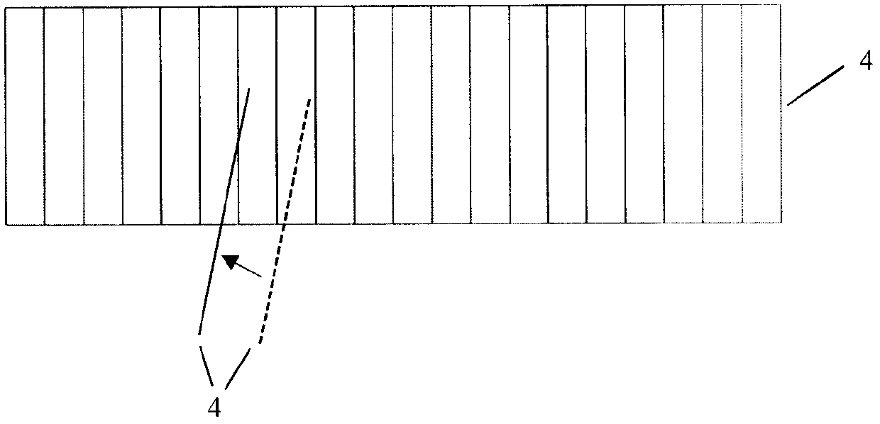
[0030] Warp yarn 5 is passed through reed 4 according to the requirement of warp density, and is suspended on the yarn hanging point 9 on the machine chassis 7 . The up and down reciprocating motion of the machine chassis 7 drives the warp yarn 5 to reciprocate up and down, and 6 or 4 channels are formed between the warp yarns 5 during the up and down reciprocating process. At this time, the weft yarn 3 is passed through the channels in turn and left therein. Finally, promote steel reed 4 to tighten weft yarn 3, reach the designed weft yarn density.
[0031] design figure 2 Shown is a schematic diagram of the fabric structure used in this embodiment, which is a layer-layer orthogonal angle interlocking structure, but the weaving method of the present invention is not limited to a certain angle interlocking structure, and is suitable for fabrics including through-thickness bias angle interlocking fabrics , P layer bias angle interlocking fabric, through-thickness bias angle interlocking fabric with weft insertion, P layer bias angle interlocking fabric with weft insertion, P layer orthogonal angle interlocking fabric, P layer orthogonal with weft insertion Any of the corner interlocking fabrics, etc. (see Yang Caiyun et al., Structural Design and New Weaving Technology of 3D Angle Interlocking Structure Prefabricated Parts for Composite Materials [J]. Journal of Donghua University, 2005, 31(5): 53 -58.).
[0032] Repeat the above operations until reaching the part where the cross-section of the workpiece changes. like image 3 As shown, the subtraction operation is performed on the yarn at the yarn reduction point I, and then the yarn transfer operation is performed on the yarn at the yarn transfer point II to the yarn hanging point at the same position in the adjacent column as shown Figure 4 As shown, the operation of changing the reed 10 is carried out to the moved yarn simultaneously, as Figure 5 As shown, the same row or multiple rows of warp yarns are located between the same reed teeth to ensure that the warp density of the workpiece remains unchanged. Repeat the above operations according to the section change design, and complete the yarn reduction and yarn transfer operations of all yarn reduction points this time. The positions of the yarn reduction points are shown in Table 1.
[0033] Table 1 The position of the yarn reduction point of the workpiece in this embodiment
[0034]
[0035] Carry out corresponding yarn reduction, yarn transfer, and weft insertion operations according to the designed yarn reduction point positions until all yarn reduction points are completed and the design length of the part is reached, and the designed trapezoidal body part is obtained.

PUM

no PUM

Description & Claims & Application Information

We can also present the details of the Description, Claims and Application information to help users get a comprehensive understanding of the technical details of the patent, such as background art, summary of invention, brief description of drawings, description of embodiments, and other original content. On the other hand, users can also determine the specific scope of protection of the technology through the list of claims; as well as understand the changes in the life cycle of the technology with the presentation of the patent timeline. Login to view more.

Similar technology patents

A kind of method for oxidative degumming of ramie by utilizing selective oxidant

InactiveCN106435755BSave energy and chemical consumptionLess fiber damageFibre treatment to obtain bast fibreCombingCellulose
Owner:DONGHUA UNIV

Bleaching technology of rose fiber knitted fabric

InactiveCN105696303AGood bleaching effect and stabilityLess fiber damageBleaching apparatusChemistrySodium silicate
Owner:江阴市长泾花园毛纺织有限公司

Progressive axial flow scutcher

PendingCN114438626AGood effectLess fiber damageFibre cleaning and opening machine combinationsFibre cleaning/opening machinesStructural engineeringFiber
Owner:YANCHENG KINGDA TEXTILE MACHINERY MFG

Paper pulp raw material cleaning treating method

ActiveCN101135117ALess fiber damageIncreased fiber lengthRaw material pretreatmentIonNon-ferrous metal
Owner:FUJIAN QINGSHAN PAPER INDUSTRY CO LTD

Easy-to-dye regenerative cellulose fibers and preparation method thereof

InactiveCN109321992ALess fiber damageIncrease the number ofArtificial filaments from cellulose solutionsArtifical filament manufactureRegenerated celluloseEnvironmentally friendly
Owner:山东瑞派新材料科技有限公司

Classification and recommendation of technical efficacy words

  • Improve quality and performance
  • Less fiber damage

Quenching process of H13 steel aluminum alloy die-casting die

InactiveCN106755880AThe quenching process is simpleImprove quality and performanceFurnace typesHeat treatment furnacesQuenchingStress relief
Owner:巴南区伟鹏机械加工厂

Full-cotton woven fabric bioenzyme continuous padding and decatizing pretreatment process

InactiveCN1528972AGood pretreatment effectLess fiber damageBiochemical fibre treatmentWoven fabricRefinery
Owner:JIANGNAN UNIV

New processing method for spinning ramee

InactiveCN1540050ALess fiber damageHigh uniformity of fiber lengthDrafting machinesYarnSmall footprintRamie
Owner:DONGHUA UNIV
Why Eureka
Try Eureka