Rigidity-reinforced type bridge head structure for operating highway and governing bump at bridge head and construction method

A bridge head jumping and construction method technology, which is applied to roads, bridges, roads, etc., can solve the problems of high maintenance cost, low maintenance cost, poor reliability, etc., and achieve the effect of easy operation, preventing rainwater seepage, and eliminating looseness

Pending Publication Date: 2018-02-27
ZHEJIANG INST OF COMM
View PDF10 Cites 8 Cited by
  • Summary
  • Abstract
  • Description
  • Claims
  • Application Information

AI Technical Summary

Problems solved by technology

[0004] In order to overcome the disadvantages of poor reliability and high maintenance cost of the existing solutions for vehicle jumping at the bridge head of the operating road, the present invention provides a rigidity reinforcement for controlling the vehicle jumping at the bridge head of the operating road with good reliability and low maintenance cost Type bridge head structure and construction method

Method used


Image

  • Rigidity-reinforced type bridge head structure for operating highway and governing bump at bridge head and construction method
  • Rigidity-reinforced type bridge head structure for operating highway and governing bump at bridge head and construction method
  • Rigidity-reinforced type bridge head structure for operating highway and governing bump at bridge head and construction method

Examples


Embodiment 1

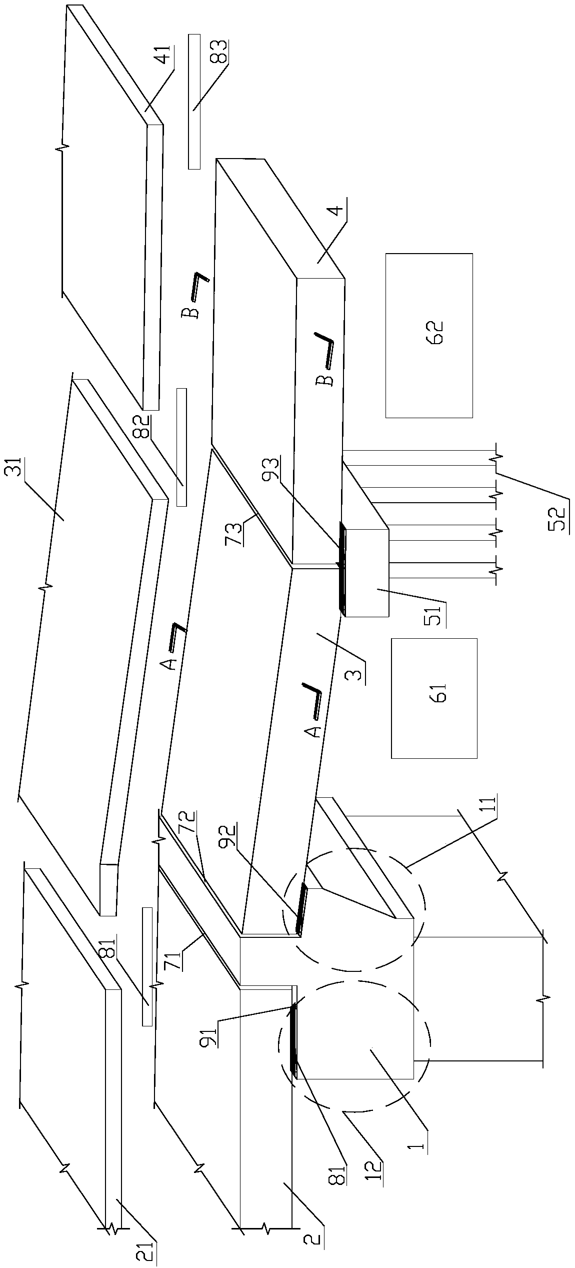
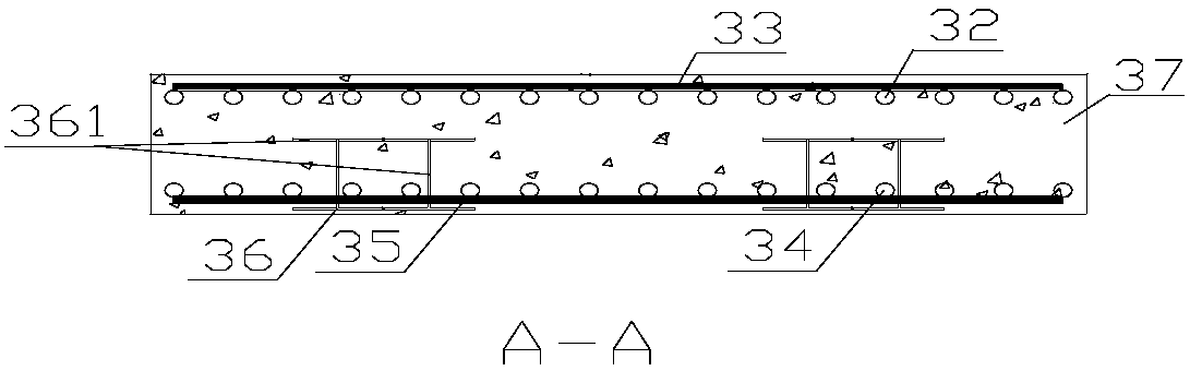
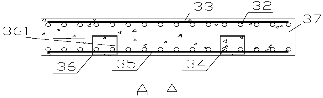
[0051] Refer to as Figure 1 ~ Figure 4 , Figure 8 ~ Figure 11 as well as Figure 13 , a rigidity-reinforced bridge head structure used to control bridge head jumping in operation roads, including abutment 1, abutment corbel 11, abutment support 12; bridge side span slab 2, bridge deck pavement 21; Slab 3, first-order pavement layer 31, upper longitudinal reinforcement 32, upper transverse reinforcement 33, lower longitudinal reinforcement 34, lower transverse reinforcement 35, concealed beam 36, concealed beam member 361, concrete 37 (or concealed beam upper reinforcement 381, concealed Beam upper reinforcement 382, ​​concealed beam stirrup 383 and concrete 37); second-order slab 4, second-order pavement layer 41, upper longitudinal reinforcement 2 42, upper transverse reinforcement 2 43, lower longitudinal reinforcement 2 43, lower transverse reinforcement 2 44 ; supporting platform 51, foundation 52; roadbed one 61, roadbed two 62; first expansion joint 71, second expans...

Embodiment 2

[0063] refer to Figure 5 to Figure 12 and Figure 14 As shown, the bridge is two-way six-lane, with a total width of 22.5m. It is a rigidity-reinforced bridge head structure used for operating roads to control bridge head jumping, including abutment 1, abutment corbel 11, and abutment support 12; Bridge side span slab 2, bridge deck pavement 21; first-order slab 3, first-order pavement layer 31, upper longitudinal reinforcement 32, upper transverse reinforcement 33, lower longitudinal reinforcement 34, lower transverse reinforcement 35, concealed beam 36, concealed Beam member 361, concrete 37 (or concealed beam upper reinforcement 381, concealed beam upper reinforcement 382, ​​concealed beam stirrup 383 and concrete 37); second-order slab 4, second-order pavement layer 41, upper longitudinal reinforcement 2 42, upper transverse Reinforcement 2 43, lower longitudinal reinforcement 2 43, lower transverse reinforcement 2 44; supporting platform 51, foundation 52; subgrade 1 61...

Embodiment 3

[0075] A construction method for a rigidity-reinforced bridge head structure used for bridge head jumping in operation of road management, comprising the following steps:

[0076] (1) Carry out ground treatment to the soft soil foundation, fill the roadbed and carry out surcharge preloading on the soft soil foundation;

[0077] (2) After the preload period expires, excavate the subgrade, construct the piles, abutments, beam slabs and expansion joints of the bridge; pre-embed dowel bars on the side of the abutment back;

[0078] (3) Backfill with graded crushed stone, and carry out layered rolling, and the compaction degree reaches the design standard;

[0079] (4) Set up the foundation of the supporting platform at the abutment end of the abutment in the range where the settlement increases near the abutment along the vehicle driving direction, and then carry out the cast-in-place and maintenance work of the supporting platform;

[0080] (5) Simultaneously with (4), and then ...


PUM


Abstract

The invention discloses a rigidity-reinforced type bridge head structure for operating a highway and governing a bump at a bridge head. The structure includes a bridge abutment, a bridge edge girder crossing board, a roadbed, a bridge surface paving structure, a first-level butting board, a second-level butting board, a first-level pavement layer, a second-level pavement layer and a supporting platform; the bridge edge girder crossing board is erected on a bridge abutment supporting base, and a bridge surface paving structure is paved on the bridge edge girder crossing board; the first-level butting board is erected between the bridge abutment and the supporting platform, one end of the first-level butting board is erected on a bridge abutment bracket; a far end of the first-level buttingboard is erected on the supporting platform, and the first-level pavement layer is paved on the first-level butting board; one end of the second-level butting board is erected on the supporting platform, the other end of the second-level butting board is erected on the roadbed, and the second-level pavement layer is paved on the second-level butting board; expansion joints exist between the bridgeedge girder crossing board and the bridge abutment, between the first-level butting board and a bridge abutment back, and between the first-level butting board and the second-level butting board. Theinvention also provides a construction method of the rigidity-reinforced type bridge head structure for operating the highway and governing the bump at the bridge head. The structure is great in reliability and low in maintenance cost.

Description

technical field [0001] The invention belongs to the technical field of connection between bridge engineering and subgrade engineering, and in particular relates to a rigidity-reinforced bridge head structure and a construction method for controlling vehicle jumps at the bridge head of operating roads. Background technique [0002] The problem of vehicle jumping at the bridge head of the operating road is one of the more common problems in the quality of road construction at home and abroad. The main hazard is that when the vehicle passes the bridge and the abutment subgrade junction, due to the difference between the abutment structure and the settlement of the embankment behind the abutment, there is a step or an excessive longitudinal slope difference. Instantaneous weightlessness causes sudden jumps and bumps of vehicles, which greatly reduces the speed of vehicles and the capacity of roads, and also greatly reduces the comfort of driving, which ultimately affects the eco...

Claims


Application Information

Patent Timeline
Patent Type & Authority Applications(China)
IPC IPC(8): E01D19/00E01D19/02E01C3/00E01D21/00
CPCE01C3/00E01D19/00E01D19/02E01D21/00
Inventor 杭振园陆森强朱汉华赵伟
Owner ZHEJIANG INST OF COMM
Why Eureka
Try Eureka