High-space-utilization power electronic capacitor

A technology of power electronics and capacitors, applied in the field of high space utilization power electronic capacitors, can solve the problems of not being able to increase the capacity, increase the weight and cost of power electronic capacitors, and reduce the space utilization of power electronic capacitors.

Inactive Publication Date: 2018-02-27
严建华
View PDF0 Cites 2 Cited by
  • Summary
  • Abstract
  • Description
  • Claims
  • Application Information

AI Technical Summary

Problems solved by technology

[0003] At the same time, power electronic capacitors commonly used in the market are generally used (see image 3 ) is formed by arranging capacitor cores, which is a relatively simple and convenient core arrangement, but this arrangement results in space between cores (see image 3 Middle 12) is very large, and requires a large number of filling layers to fill, and the density of the filling layer is far great

Method used


Image

  • High-space-utilization power electronic capacitor
  • High-space-utilization power electronic capacitor
  • High-space-utilization power electronic capacitor

Examples


Example Embodiment

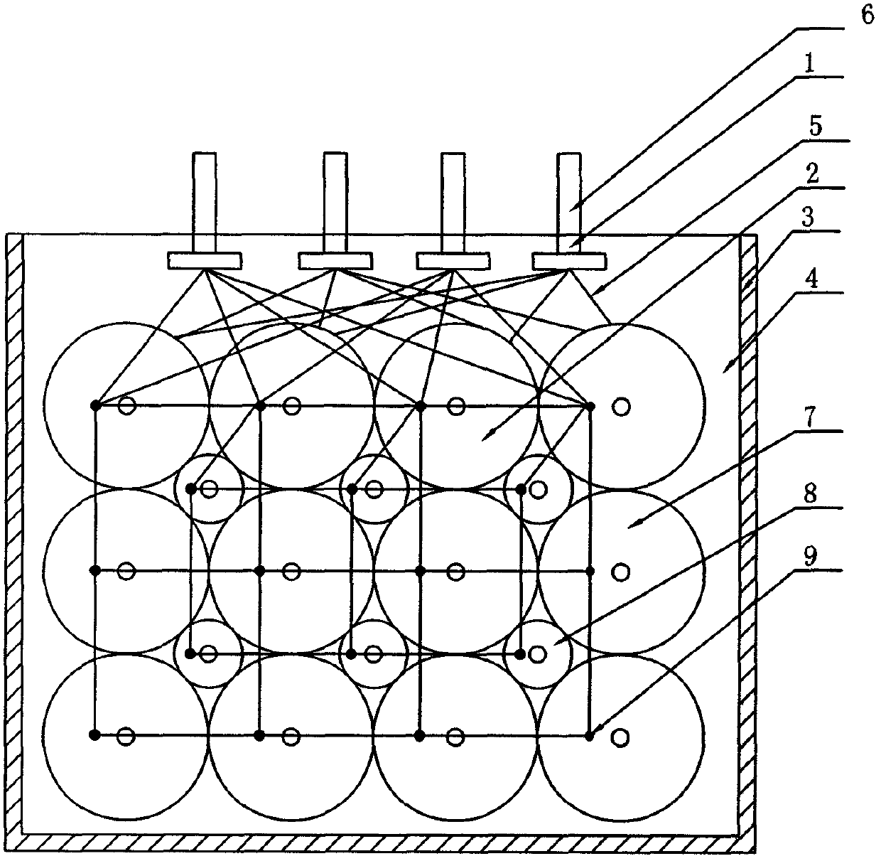
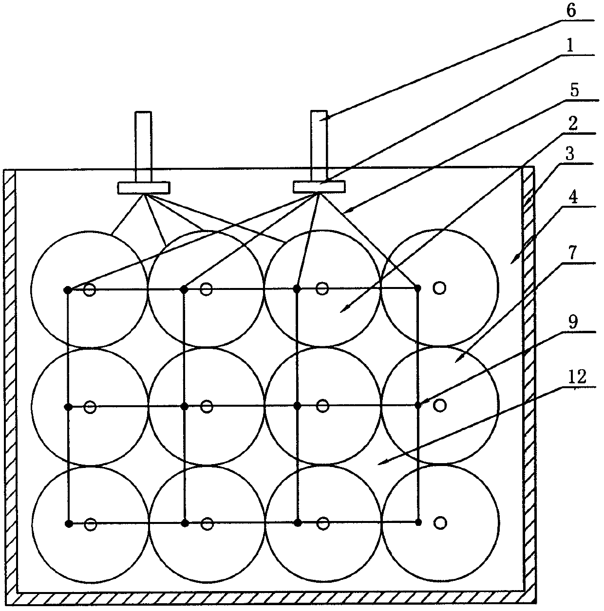
[0018] The high space utilization power electronic capacitor of the embodiment of the present invention is such as image 3 with Figure 4 The power electronic capacitor shown in the prior art is improved on the basis of the structure, mainly in the space 12 between its 12 large cylindrical capacitor cores 7 squeezed into 6 small capacitor cores which are also cylindrical. Structure like figure 1 with figure 2 Shown:

[0019] ——The capacitor core assembly 2 located in the inner cavity of the shell 3 is composed of 12 large cylindrical capacitor cores 7 and 6 small capacitor cores 8 which are also cylindrical. Twelve large capacitor cores 7 are closely distributed in 3 horizontal rows and 4 vertical columns, and 6 small capacitor cores 8 are squeezed in the space between the large capacitor cores 7. The gold-sprayed layers on the front and rear ends of the large and small capacitor cores are respectively welded at the welding points 9 with wires distributed in a rectangular grid ...


PUM


Abstract

A power electronic capacitor with high space utilization rate, comprising a capacitor core assembly (2) located in the inner cavity of a housing (3) and a two-pole electrode assembly (1), the electrode assemblies (1) of each pole include capacitor cores The electrical connecting wires (5) connected to the gold-sprayed layer at one end and the electrode leads (6) connected to these electrical connecting wires, the capacitor core assembly (2) is composed of a plurality of capacitor cores, and between each capacitor core and The gap perfusion filling layer (4) between them and the inner wall of the shell (3) is characterized in that: the capacitor core includes a large capacitor core (7) and a small capacitor core (8), and the small capacitor core ( 8) The space between the major capacitor cores (7). The design reduces the volume and inductance of the capacitor, is beneficial to the heat dissipation of the capacitor, improves the reliability of the capacitor and reduces the cost.

Description

technical field [0001] The invention relates to a power electronic capacitor, especially a power electronic capacitor with high space utilization rate. In the international patent classification table, the classification can belong to H01G4 / 224 and H01G4 / 228. Background technique [0002] Power electronic capacitors commonly used in the market currently have only two electrode leads, which is a relatively simple and convenient way to lead out, but when the current of the ripple component passes through the two electrode leads, the leads of the two electrodes The method will cause this kind of capacitor to generate a large self-parasitic inductance, generally its own inductance is much greater than 100nH, once this kind of capacitor is operated under high-frequency conditions, the temperature rise will be too fast, too high, or even greatly affected its own lifespan. However, since the core of this capacitor adopts non-inductive winding, the self-inductance of a single core ...

Claims


Application Information

Patent Timeline
IPC IPC(8): H01G4/224H01G4/228
CPCH01G4/224H01G4/228
Inventor 蒋晋辉
Owner 严建华
Why Eureka
Try Eureka