LED luminous device

A light-emitting device, LED chip technology, applied in electrical components, electrical solid-state devices, circuits, etc., can solve the problems of detachment of the diamond-like carbon layer, damage to the LED light source, etc., to improve adhesion, speed up heat dissipation, and improve thermal expansion coefficients. Effect

Inactive Publication Date: 2018-02-27
夏烬楚
View PDF0 Cites 0 Cited by
  • Summary
  • Abstract
  • Description
  • Claims
  • Application Information

AI Technical Summary

Problems solved by technology

[0004] However, the thermal expansion coefficients of the metal substrate and the diamond-like layer are several times different. When the heat generated by the LED chip is dissipated through the metal substrate, the diamond-like layer is prone to detachment from the metal substrate, resulting in damage to the LED light source.

Method used


Image

  • LED luminous device

Examples


Embodiment Construction

[0015] The following will clearly and completely describe the technical solutions in the embodiments of the present invention with reference to the accompanying drawings in the embodiments of the present invention. Obviously, the described embodiments are only some, not all, embodiments of the present invention. Based on the embodiments of the present invention, all other embodiments obtained by persons of ordinary skill in the art without making creative efforts belong to the protection scope of the present invention.

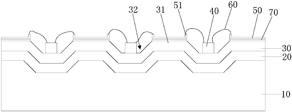
[0016] refer to figure 1 , is a schematic structural view of the LED lighting device provided by the embodiment of the present invention. The LED lighting device of this embodiment includes a ceramic substrate 10 , an aluminum nitride isolation layer 20 and a diamond-like carbon layer 30 stacked in sequence from bottom to top. Preferably, the ceramic base 10 can be made of transparent ceramics. The thickness of the aluminum nitride isolation layer 20 is 10-3...


PUM

PropertyMeasurementUnit
thicknessaaaaaaaaaa

Abstract

The invention discloses an LED lighting device. It includes a ceramic substrate, an aluminum nitride isolation layer and a diamond-like layer stacked in sequence from bottom to top. The upper surface of the diamond-like layer is fixed with a plurality of alternately spaced LED chips and metal film electrodes. The P electrode of each LED chip The N electrode and the N electrode are electrically connected to the metal film electrodes on both sides. The upper surface of the diamond-like layer is provided with a plurality of outwardly protruding protrusions, and grooves are formed between adjacent two protrusions. The LED chip is arranged on the diamond-like layer. In the groove, the metal thin film electrode is arranged on the protruding part of the diamond-like layer, wherein the adhesion between the aluminum nitride isolation layer and the ceramic substrate and the diamond-like layer are greater than that of the ceramic substrate and the diamond-like layer. The adhesion generated during the attachment, and the thermal expansion coefficient of the aluminum nitride isolation layer is between the ceramic substrate and the diamond-like carbon layer. The invention can prevent the diamond-like carbon layer from detaching while accelerating heat dissipation.

Description

technical field [0001] The invention relates to the technical field of semiconductors, in particular to an LED lighting device. Background technique [0002] With the continuous improvement of light efficiency of LEDs (Light Emitting Diodes, light emitting diodes), in the field of general lighting, there is a trend of using LEDs to replace traditional light emitting devices. However, the LED light source usually generates a lot of heat when it is working, and the heat needs to be dissipated in time, otherwise it will affect the normal operation and service life of the LED light source. [0003] The existing LED light source includes a metal substrate and a diamond-like carbon layer arranged on the metal substrate, and an LED chip is arranged on the diamond-like carbon layer. Diamond-like carbon has good thermal conductivity. Therefore, the heat dissipation effect of the LED light source using it is obvious. [0004] However, the thermal expansion coefficients of the metal...

Claims


Application Information

Patent Timeline
Patent Type & Authority Applications(China)
IPC IPC(8): H01L25/075H01L33/64H01L33/62
CPCH01L25/0753H01L33/62H01L33/641H01L33/642
Inventor 夏烬楚
Owner 夏烬楚
Why Eureka
Try Eureka