Tubular type micro air bubble generator

A technology of micro-bubbles and generators, applied in fluid mixers, chemical instruments and methods, mixers, etc., can solve the problems that micro-bubbles are difficult to meet the needs of water purification treatment, poor quality of bubbles, complex structure, etc., and achieve the solution of air holes Easy to block, easy to install and operate, and improve the effect of shearing and crushing

Active Publication Date: 2018-03-02
BEIJING INSTITUTE OF PETROCHEMICAL TECHNOLOGY
View PDF2 Cites 29 Cited by
  • Summary
  • Abstract
  • Description
  • Claims
  • Application Information

AI Technical Summary

Problems solved by technology

[0003] Generally speaking, the generation methods of fine bubbles can be divided into five categories: dissolved air release type, air-entrained dispersion type, microporous air diffusion type, shear contact type, and electrolysis type. This kind of micro-bubble generator and its corresponding micro-bubble generation method generally have the disad...

Method used


Image

  • Tubular type micro air bubble generator
  • Tubular type micro air bubble generator
  • Tubular type micro air bubble generator

Examples


Embodiment 1

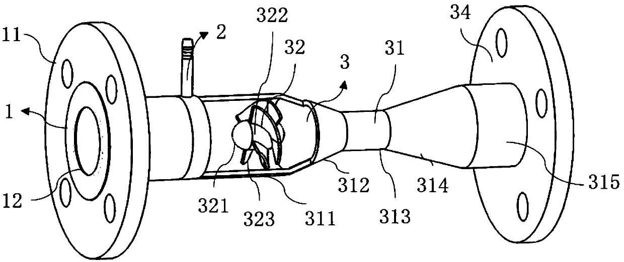
[0026] Such as figure 1 As shown, a tube-type micro-bubble generator is installed in the water purification pipeline, including a water inlet assembly 1, an annular gas injection mechanism 2 and a bubble breaking mechanism 3 which are connected coaxially in sequence; the water inlet assembly 1 It includes a water inlet flange 11 and a water inlet pipe 12. The water inlet flange 11 is connected to the water inlet end of the water purification pipeline. One end of the water inlet pipe 12 is connected to the water inlet flange 11 and the other end is connected to the annular gas injection mechanism 2.

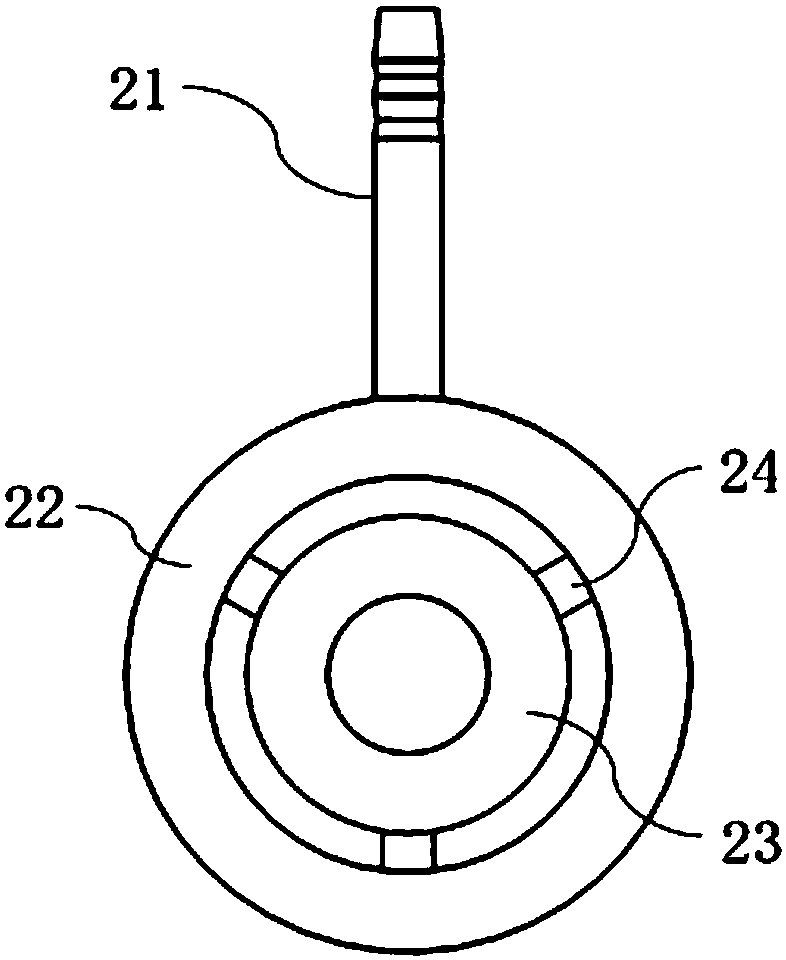
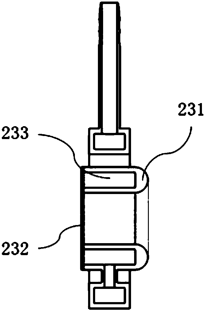
[0027] Such as figure 2 and image 3 As shown, the annular gas injection mechanism 2 includes a gas injection pipe 21, an outer ring 22, an inner ring 23 and a connecting pipe 24, the inner ring 23 and the outer ring 22 are installed concentrically, and the outer ring 22 is a cavity structure , the inner ring 23 is a ring cavity 233 with a side opening, and a microporous plate ...

specific Embodiment

[0039] Figure 5-7 In order to base on the above-mentioned design concept and structural scheme, the Computational Fluid Dynamics (CFD) simulation related display of the operation effect of the pipe-type micro-bubble generator under the specific treatment water volume was designed and developed. Specifically, the designed inlet water flow rate is 3m3 / h, the inlet pipe diameter is DN25, the inlet water pressure is 0.2MPa, the gas injection ratio is 5%, and the gas injection pressure is <0.5MPa. The figure shows the static pressure cloud diagram, velocity cloud diagram and turbulent kinetic energy cloud diagram of the bubble breaking section of the tubular microbubble generator respectively.

[0040] (1) Analysis of pressure simulation results

[0041] Figure 5 In order to intercept the static pressure distribution cloud diagram of the y=0 plane and each cross-section, it can be seen from the figure that in the Venturi flow channel, the pressure in the flow field presents a t...


PUM

PropertyMeasurementUnit
Cone angleaaaaaaaaaa
Lengthaaaaaaaaaa
Apertureaaaaaaaaaa

Abstract

The invention discloses a tubular type micro air bubble generator. The tubular type micro air bubble generator is arranged in a water purifying pipeline, and comprises a water intake assembly (1), anannular air injection mechanism (2) and an air bubble breaking mechanism (3) which are sequentially connected and coaxially arranged, wherein the annular air injection mechanism (2) comprises an air injection pipe (21), an outer ring (22), an inner ring (23) and a connecting pipe (24); the inner ring (23) and the outer ring (22) are arranged in a concentric way; the outer ring (22) is of a cavitystructure; the inner ring (23) is of a ring cavity (233) with a side opening; a micro-pore plate (232) is arranged at the side opening of the inner ring (23); the outer wall of a cavity of the outer ring (22) is communicated with the air injection pipe (21), and the inner wall of the cavity of the outer ring (22) is communicated with the ring cavity (233) of the inner ring (22) through the connecting pipe (24). The tubular type micro air bubble generator has the advantages that the structure is compact, the operation is simple, the maintenance cost is low, and the micro air bubbles with different particle sizes can be produced.

Description

technical field [0001] The invention relates to the fields of mechanical technology and water purification treatment, in particular to a tube-type micro-bubble generator. Background technique [0002] According to the definition of the Standardization Organization (ISO), fine bubbles usually refer to bubbles with a particle size of less than 100 microns. They have the characteristics of large specific surface area, high gas holdup, unbreakable, high adhesion efficiency, and high mass transfer efficiency. They are widely used in mineral flotation. Selection, water purification treatment, aquaculture and biopharmaceuticals and other fields. Especially in the field of sewage treatment, micro-bubbles are not only used to increase the dissolved oxygen content in sewage, to promote the phagocytosis and decomposition of organic impurities in sewage by aerobic microorganisms, but also to form solid or liquid suspended particles in the adhered water to form particles with a density l...

Claims


Application Information

Patent Timeline
IPC IPC(8): B01F3/04B01F5/04
CPCB01F23/23B01F23/2366B01F23/2373B01F25/3121
Inventor 陈家庆丁国栋蔡小垒姬宜朋
Owner BEIJING INSTITUTE OF PETROCHEMICAL TECHNOLOGY
Why Eureka
Try Eureka