Pipe pressure wave velocity test device and method based on pipe flow test loop

A test device, a technology for pipe flow test, applied in the direction of measurement device, fluid velocity measurement, velocity/acceleration/impact measurement, etc., which can solve problems such as large errors

Active Publication Date: 2018-03-02
CHINA UNIV OF PETROLEUM (EAST CHINA) +1
View PDF8 Cites 7 Cited by
  • Summary
  • Abstract
  • Description
  • Claims
  • Application Information

AI Technical Summary

Problems solved by technology

In applications such as computer dynamic simulation, pipeline transient flow analysis, and pipeline leak detec

Method used


Image

  • Pipe pressure wave velocity test device and method based on pipe flow test loop
  • Pipe pressure wave velocity test device and method based on pipe flow test loop
  • Pipe pressure wave velocity test device and method based on pipe flow test loop

Examples


Embodiment 1

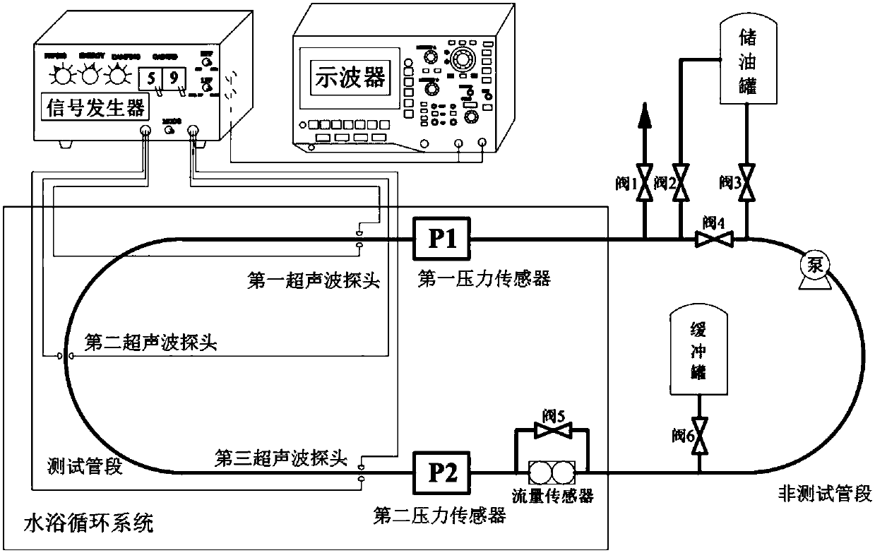
[0059] The purpose of embodiment 1 is to provide a kind of pipeline pressure wave velocity testing device based on the pipeline flow test loop, such as figure 1 As shown, the test device includes a pipe flow loop test device and an ultrasonic velocity test device.

[0060] (1) Pipe flow loop test device

[0061] The pipe flow loop test device includes a test loop system, a water bath circulation system and a data acquisition system. The test loop system, the water bath circulation system and the data acquisition system work together to complete the simulation of different operating conditions of the actual crude oil pipeline.

[0062] In this embodiment, the test loop system is used to simulate the flow conditions (temperature, pressure, shear conditions) of crude oil in the actual pipeline, including test loops, oil storage tanks, pumps, buffer tanks and several valves . Specifically, the pipe material of the test loop is 304 stainless steel pipe, its elastic modulus E is ...

Embodiment 2

[0077] The second object of the present invention is to provide a kind of pressure wave velocity test method based on pipe flow test loop, such as Figure 4 shown.

[0078] In order to achieve the above object, the present invention adopts the following technical scheme: the method is based on the pressure wave velocity testing device in the indoor pipe flow test loop, and the determination of the pressure wave velocity at different positions along the actual pipeline is realized through the following operation steps:

[0079] Step (1): Measure the viscosity of the oil at different temperatures, obtain the viscosity-temperature curve of the oil viscosity changing with temperature, and determine the abnormal point of the oil.


PUM

PropertyMeasurementUnit
Elastic modulusaaaaaaaaaa

Abstract

The invention relates to a pipe pressure wave velocity test device and method based on a pipe flow test loop. The test device comprises a pipe flow test loop device, an ultrasonic wave velocity test device and a calculation device. The pipe flow test loop device includes a test pipe system, a data acquisition system and a water bath circulation system which work together to simulate different operating conditions of a pipe. The test method includes the following steps: measuring the viscosity-temperature curve of oil viscosity change with temperature and determining an abnormal point; determining the temperature distribution and residual pressure distribution along an inter-station pipe, and segmenting the inter-station pipe; using an indoor pipe flow test loop device to simulate the operating condition of an actual pipe based on the principle that the energy dissipation rate of fluid per unit volume is the same; using an ultrasonic wave velocity test device to simulate the ultrasonicwave velocity under the operating condition, and establishing an ultrasonic wave velocity database under the actual operating conditions of the pipe; and determining the sound velocity of each sectionof pipe, and calculating the pressure wave velocity of each section of pipe based on the pipe parameters.

Description

technical field [0001] The invention belongs to the technical field of crude oil and refined oil pipeline transportation, and in particular relates to a test device and method for determining the pressure wave velocity along a pipeline based on an indoor pipeline flow test loop. Background technique [0002] Pressure wave transmission velocity, referred to as pressure wave velocity, is one of the most sensitive and important parameters in the analysis of crude oil or refined oil pipeline transportation and transient dynamic characteristics. There are many factors affecting the pressure wave velocity of crude oil pipelines, not only related to the physical properties of the fluid itself, such as pressure, temperature, gas content, etc., but also related to factors such as the geometric parameters of the pipeline, the mechanical properties of the material, and the support method of the structure. Therefore, it is difficult to accurately measure the pressure wave velocity of th...

Claims


Application Information

Patent Timeline
IPC IPC(8): G01P5/24
CPCG01P5/245
Inventor 滕厚兴刘刚陈放张一智卢兴国陈雷
Owner CHINA UNIV OF PETROLEUM (EAST CHINA)
Why Eureka
Try Eureka