Intelligent field ploughing equipment based on solar energy

A solar energy and equipment technology, applied in the field of tillers, can solve the problem of large energy consumption of tillers, achieve a broad market space and practical value, and prevent people from being injured.

Inactive Publication Date: 2018-03-06
何宏志
View PDF0 Cites 3 Cited by
  • Summary
  • Abstract
  • Description
  • Claims
  • Application Information

AI Technical Summary

Problems solved by technology

[0003] The purpose of the present invention is to provide intelligent tillage equipment based on solar energy, to solve the problem of huge energy consumption of cultivators in the prior art, and to achieve the purpose of reducing energy consumption of tillers

Method used


Image

  • Intelligent field ploughing equipment based on solar energy

Examples


Embodiment 1

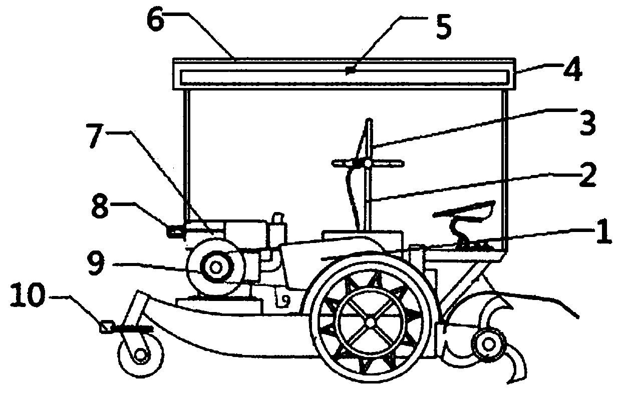
[0015] Such as figure 1 The shown intelligent plowing equipment based on solar energy includes plowing machine body 1, plowing joystick 2, LCD touch screen 3, plowing machine roof 4, battery device 5, solar panel 6, plowing machine power 7, Front view camera 8, cultivating machine power drive shaft emergency brake 9, infrared temperature sensor 10, characterized in that: the upper end of the driving wheel on the left front of the cultivating machine body 1 is horizontally arranged with a cylindrical infrared temperature sensor to the left. On the upper surface of the left side of the field machine body 1, a plowing machine power 7 is arranged, and a ring-shaped plowing machine power 7 drive shaft emergency brake is arranged on the periphery of the drive shaft on the front surface of the plowing machine power 7. A front-view camera 8 is installed horizontally to the left on the left surface of the motor force 7, and a rectangular sheet-shaped cultivator roof 4 is arranged on th...


PUM


Abstract

The invention discloses intelligent field ploughing equipment based on solar energy. When a system judges that a cultivator is in a dangerous working state, a power drive shaft emergency brake startsand is tightly nested at the periphery of an electrical machine drive shaft of the cultivator to make the electrical machine drive shaft stops rotation, and people are prevented from injuring; and thewhole field ploughing equipment has a simple structure, high security and wide market space and practical value.

Description

technical field [0001] The invention relates to the field of tillage machines, in particular to intelligent tillage equipment based on solar energy. Background technique [0002] The total power of agricultural machinery refers to the sum of the power of various power machinery mainly used in agriculture, forestry, animal husbandry and fishery. Including farming machinery, drainage and irrigation machinery, harvesting machinery, agricultural transport machinery, plant protection machinery, animal husbandry machinery, forestry machinery, fishing machinery and other agricultural machinery calculate〕. Since the reform and opening up, as the country has improved the level of agricultural mechanization and accelerated the implementation of rural infrastructure policies, my country's agricultural machinery industry has developed significantly, and has formed internal combustion engines, tractors, transportation machinery, harvesting machinery, animal husbandry machinery, and trac...

Claims


Application Information

Patent Timeline
Patent Type & Authority Applications(China)
IPC IPC(8): A01B71/00
CPCY02P60/12A01B71/00
Inventor 何宏志
Owner 何宏志
Why Eureka
Try Eureka