Device and method for cutting out contours from flat substrates using a laser

A substrate and profile technology, applied in laser welding equipment, welding equipment, glass manufacturing equipment, etc., can solve problems such as uneven cutting gaps

Active Publication Date: 2018-03-06
CORNING LASER TECH
View PDF8 Cites 5 Cited by
  • Summary
  • Abstract
  • Description
  • Claims
  • Application Information

AI Technical Summary

Problems solved by technology

However, this method has disadvantages in the case of many materials, resulting in, for example, impurities due to particle formation during ablation or cut edges with undesired micro-cracks or melted edges such that the cut gap is over the thickness of the material. uneven

Method used


Image

  • Device and method for cutting out contours from flat substrates using a laser
  • Device and method for cutting out contours from flat substrates using a laser
  • Device and method for cutting out contours from flat substrates using a laser

Examples


Embodiment Construction

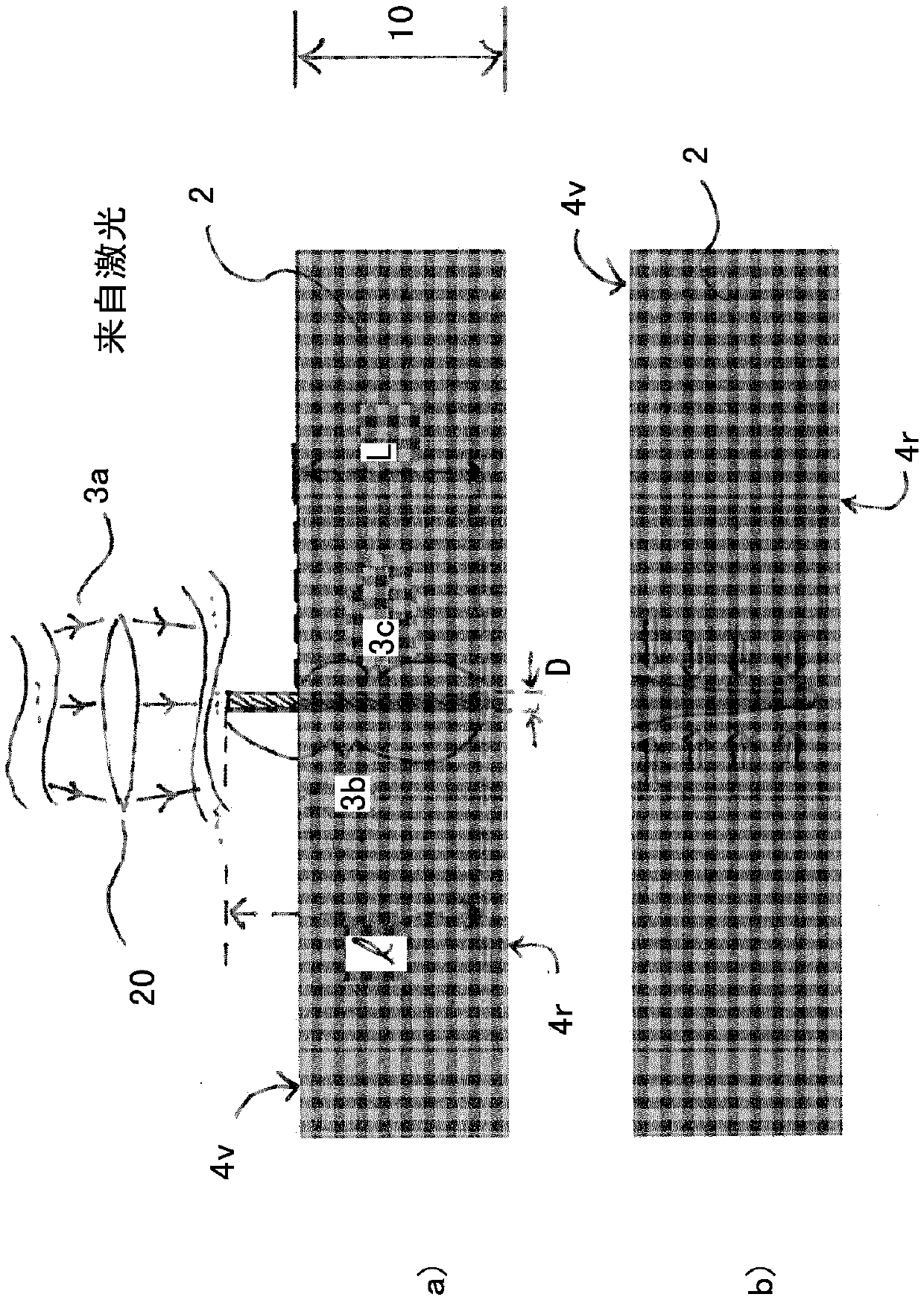
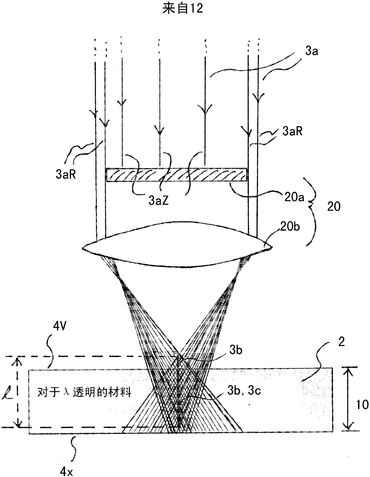
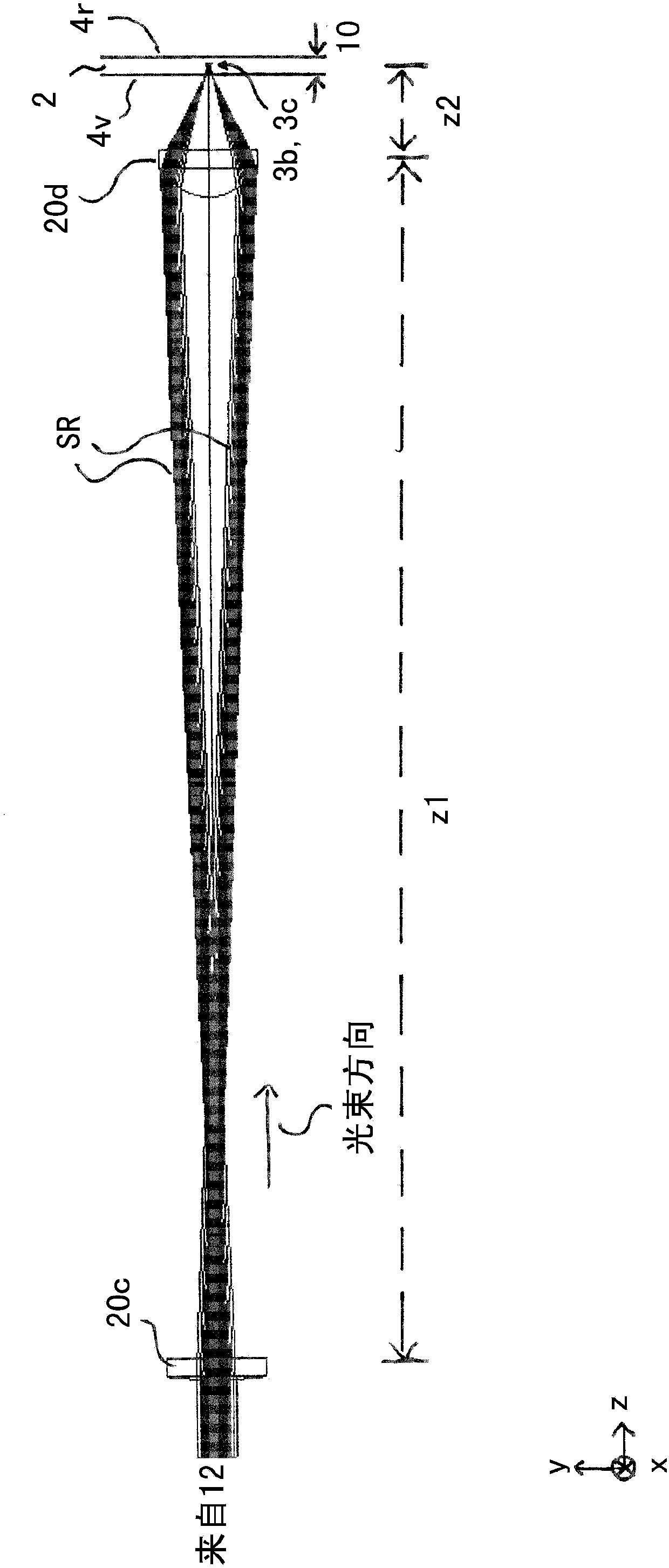
[0120] figure 1 Outline the basic procedure for steps (a), (b) and (d). The laser 12 ( Figure 10 , not shown here) emitted laser beam 3 is impinged on the optical arrangement 20 of the present invention. The optical arrangement 20 forms an extended laser beam focal line 3b from the irradiated laser beam on the beam output side over a defined extension area (length 1 of the focal line) along the beam direction. At least partially covering the laser beam focal line 3b of the laser radiation 3, the flat substrate 2 to be processed is located in the beam path following the optical arrangement. Reference numeral 4v designates the surface of the flat substrate oriented towards the optical arrangement 20 or laser and reference numeral 4r designates the rear side surface of the substrate 2 normally parallel to and spaced from the surface 4v. The substrate thickness (measured perpendicular to the surfaces 4v and 4r , ie relative to the substrate plane) is designated here with refer...


PUM

PropertyMeasurementUnit
diameteraaaaaaaaaa
diameteraaaaaaaaaa
frequencyaaaaaaaaaa

Abstract

The invention relates to a method for producing a contour (5) in a planar substrate (5) and for removing the contour from the substrate, in particular for producing an internal contour in a planar substrate and for removing the internal contour from the substrate, wherein in a contour definition step, by means of a laser beam (3) guided over the substrate, a plurality of individual zones (5-1, 5-2,....) of internal damage is produced along a contour line in the substrate material marking the contour (5) to be produced; in a crack definition step, by means of a laser beam guided over the substrate, a plurality of individual zones (6-1, 6-2,...) of internal damage is produced along each of a plurality of crack line segments (6a, 6b,..) in the substrate material leading, as viewed from the contour line, away at an angle [alpha] > 0 and into the contour to be removed; and in a material removal step performed after the contour definition step and after the crack definition step, by means ofa material-removing laser beam (7) guided over the substrate, the substrate material is removed over the entire substrate thickness along a removal line, which extends along the contour line but at adistance from the contour line and in the contour to be removed and which also preferably crosses the crack line segments.

Description

[0001] This application is a divisional application of an invention patent application with an international filing date of March 18, 2014, and a Chinese national phase application number of 201480029468.1, entitled "Equipment and method for cutting contours from flat substrates by means of laser". technical field [0002] The present invention relates to a device and a method for cutting profiles by means of a laser from a flat substrate, more particularly: from a glass substrate or a crystalline substrate. Background technique [0003] DE 10 2011 00768 A1 describes how, with the aid of a laser, semiconductor wafers, glass components and other substrates can be divided into parts by the wavelength of the laser being greatly absorbed by the material. Thus, a material removal is achieved which ultimately leads to the division of the substrate into multiple parts. However, this method has disadvantages in the case of many materials, resulting in, for example, impurities due to...

Claims


Application Information

Patent Timeline
Patent Type & Authority Applications(China)
IPC IPC(8): B23K26/38B23K26/40C03B33/02C03B33/04C03B33/09
CPCB23K26/38B23K26/40C03B33/0222C03B33/04C03B33/091C03B33/082B23K2103/50B23K2103/54B23K2103/56B23K26/53B23K26/0006C03B25/025
Inventor R·伯梅
Owner CORNING LASER TECH
Why Eureka
Try Eureka