Electrically controlled brake power-assisted system and vehicle brake system

A technology of electric control and electronic control unit, which is applied in the direction of brake transmission, brake, vehicle parts, etc., can solve the problems of high technical requirements, unrealization, and high cost of screw screws, and achieve compact structure, uniform wear, and low noise. Effect

Active Publication Date: 2018-03-06
SAIC GENERAL MOTORS +1
View PDF5 Cites 11 Cited by
  • Summary
  • Abstract
  • Description
  • Claims
  • Application Information

AI Technical Summary

Problems solved by technology

However, if it is necessary to realize more complex braking system functions, such as braking energy recovery, this structure cannot be realized.
[0007] In addition, the existing traditional electronic brake bo

Method used


Image

  • Electrically controlled brake power-assisted system and vehicle brake system
  • Electrically controlled brake power-assisted system and vehicle brake system
  • Electrically controlled brake power-assisted system and vehicle brake system

Examples


Embodiment Construction

[0044] The technical solutions of an electronically controlled brake booster system and a vehicle brake system involved in the present invention will be further described in detail below in conjunction with the accompanying drawings and embodiments.

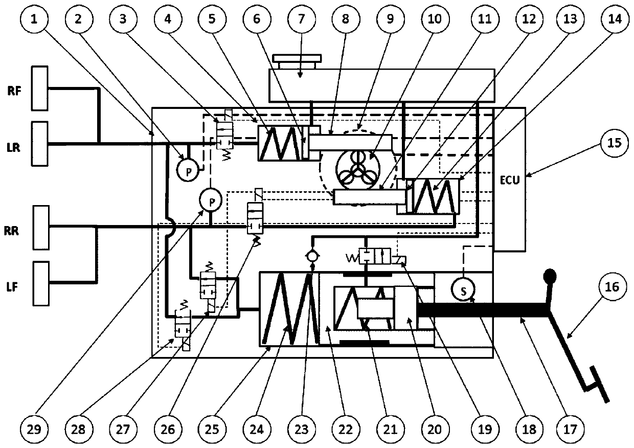
[0045] see figure 1 As shown, a vehicle brake system provided according to an embodiment of the present invention includes an electronically controlled brake booster system 1, a right front left rear power brake cylinder pipeline pressure sensor 2, a right front left rear power brake cylinder tube Road normally closed solenoid valve 3, right front left rear booster brake cylinder 4, right front left rear booster brake cylinder return spring 5, right front left rear booster brake cylinder piston 6, brake fluid pot 7, right front left rear booster brake Cylinder push rod (rack) 8, drive motor 9, planetary gear reduction mechanism 10, left front and right rear power-assisted brake cylinder push rod (rack) 11, left front and right re...


PUM


Abstract

The invention discloses an electrically controlled brake power-assisted system and relates to the field of vehicle brake systems. The electrically controlled brake power-assisted system comprises a pedal simulator, an electronic control unit, a driving motor and a power-assisted brake cylinder, wherein the pedal simulator is constructed to be integrated together with a brake master cylinder, and apedal simulator cylinder body serves as a piston of the brake master cylinder; an output end of the driving motor is connected with a planet gear reducing mechanism, and the planet gear reducing mechanism is connected with the power-assisted brake cylinder through racks; and in a normal brake work mode, the pedal simulator absorbs the stroke of a brake pedal push rod, the electronic control unitsends an operating instruction to the driving motor according to the stroke of the pedal push rod, and the planet gear reducing mechanism is matched with the racks to drive the piston of the power-assisted brake cylinder to generate brake pressure, thereby realizing the brake of a vehicle.

Description

technical field [0001] The present invention relates to the field of vehicle brake systems, in particular to an electronically controlled brake booster system for automobiles, which is applicable to various types of motor vehicles, including new energy vehicles such as hybrid electric vehicles; Vehicle braking system that controls the brake assist system. Background technique [0002] With the breakthrough of new energy vehicle technology, compared with traditional fuel vehicles, the specific advantages of new energy vehicles are becoming more and more obvious, and the share of new energy vehicles is also increasing year by year. Due to the substantial difference in power drive between new energy vehicles and traditional fuel vehicles, some structures or components that can be used on traditional fuel vehicles are not suitable for new energy vehicles. [0003] For example, in the field of automotive braking, traditional fuel vehicles use a vacuum booster for brake boosting,...

Claims


Application Information

Patent Timeline
IPC IPC(8): B60T13/68
CPCB60T13/686
Inventor 谢骋毛向阳杨春伟崔海峰赵向东袁旭亮
Owner SAIC GENERAL MOTORS
Why Eureka
Try Eureka