A rapid emergency grouting plugging method for foundation pit water gushing

A foundation pit and grouting technology, which is applied in the direction of infrastructure engineering and construction, can solve the problems of water leakage on the side wall of the foundation pit, large flow and high pressure water gushing, collapse of the side wall of the foundation pit, etc., and achieve grouting sealing Save time, reduce economic losses, and ensure the quality of water plugging

Active Publication Date: 2019-11-19
SHANDONG UNIV
View PDF7 Cites 0 Cited by
  • Summary
  • Abstract
  • Description
  • Claims
  • Application Information

AI Technical Summary

Problems solved by technology

[0002] During the excavation of the foundation pit, due to poor geological conditions, lateral runoff of groundwater, or poor quality of piles formed by jet grouting piles, water leakage or even large flow and high pressure water gushing on the side wall of the foundation pit often occurs. Due to untimely treatment It is very easy to cause the side wall of the foundation pit to collapse and cause major safety accidents. For such situations, it is necessary to achieve rapid rescue and reduce losses as much as possible. As an effective means of water blocking and reinforcement, the grouting method has been used in underground engineering water disasters However, there are still many technical difficulties, such as the inability to effectively determine the water guide channel, the ineffective diffusion of the slurry, etc., which make the rescue work unable to be carried out smoothly, delay the best treatment period of the dangerous situation, and cause major safety accidents

Method used


Image

  • A rapid emergency grouting plugging method for foundation pit water gushing
  • A rapid emergency grouting plugging method for foundation pit water gushing
  • A rapid emergency grouting plugging method for foundation pit water gushing

Examples


Embodiment

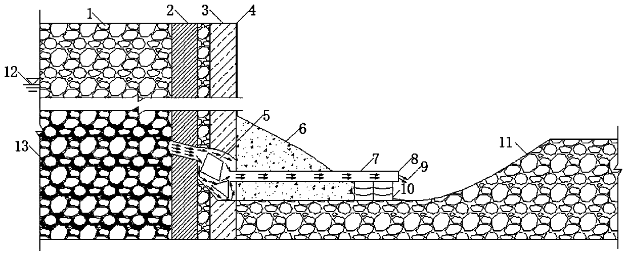
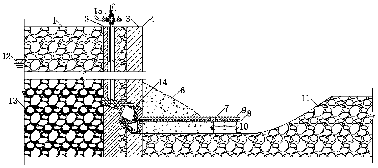
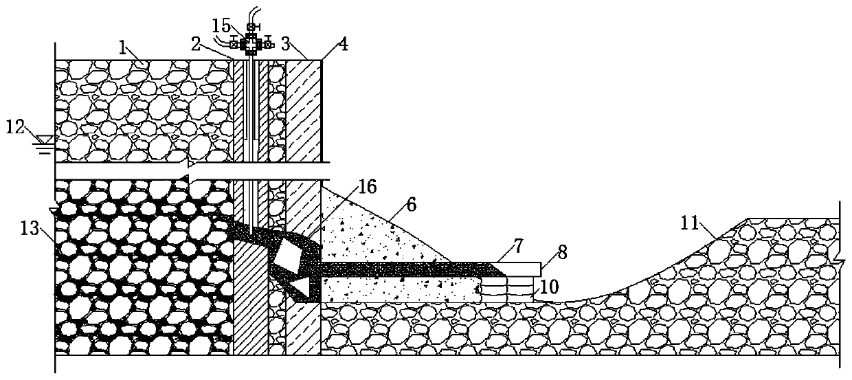
[0045] Lingshanwei Station of Qingdao Metro Line R3 is 195 meters long and is a two-story underground station; the long-distance open-cut section is 322 meters long and has a single-story frame structure. The landform is a coastal accumulation area, mostly composed of coastal sediments and river sediments, which is manifested as a coastal swamp landform. The original ground elevation of the station is +5.0m, and the strata from top to bottom are: 3m of plain fill, 3m of medium-coarse sand containing silt, 3m of silty clay, 6m of medium-coarse sand (mud content 8%), and cohesive gravel Sand 2.2m, strongly weathered tuff 2.6m. The basement is located at the junction of the gravel sand layer and the strongly weathered layer.

[0046] At 8 a.m. on May 23, 2016, when the western end of the foundation pit was dug down to -3.5m, two gushes of water were found on the side wall, pouring into the foundation pit along the piles, with a total flow of about 40m 3 / h, the average water pr...


PUM


Abstract

The invention discloses a quick emergency rescuing, grouting and plugging method for foundation pit water bursting. The quick emergency rescuing, grouting and plugging method comprises the following steps that after dangerous circumstances occur, back pressure measures are taken in time, and a pressure relieving pipe is arranged; the water outlet point position of a foundation pit is determined, ground surface drilling construction is conducted at the position, a certain distance away from a filling pile, of the side wall of the foundation pit, that is, the axis position of a jet grouting pile, and when a drilling construction tool arrives at a water guiding channel, a casing pipe with a certain length is put down, and a PVC pipe is put down to the water guiding channel; a grouting pump pipeline is connected with the PVC pipe, and a grouting pump is started to pump cement paste single fluid; and when it is observed that cement paste flows out of the pressure relieving pipe, quick coagulating type grout starts to be injected, the grout is quickly coagulated and hardened in the water guiding channel till no water flows out of the pressure relieving pipe any more, and then complete plugging on the water guiding channel is achieved. According to the method, quick plugging on foundation pit side wall water bursting can be achieved, and the method has an important role in disaster emergency treatment of foundation pit side wall water bursting.

Description

technical field [0001] The invention relates to a rapid emergency grouting sealing method for water gushing in foundation pits, which belongs to the field of water prevention and control for foundation pits, tunnels and other underground projects. Background technique [0002] During the excavation of the foundation pit, due to poor geological conditions, lateral runoff of groundwater, or poor quality of piles formed by jet grouting piles, water leakage or even large flow and high pressure water gushing on the side wall of the foundation pit often occurs. Due to untimely treatment It is very easy to cause the side wall of the foundation pit to collapse and cause major safety accidents. For such situations, it is necessary to achieve rapid rescue and reduce losses as much as possible. As an effective means of water blocking and reinforcement, the grouting method has been used in underground engineering water disasters However, there are still many technical difficulties, such...

Claims


Application Information

Patent Timeline
Patent Type & Authority Patents(China)
IPC IPC(8): E02D19/16E02D15/04
Inventor 张庆松刘亚南刘人太王洪波姜鹏桂大壮辛冬冬闫成伟
Owner SHANDONG UNIV
Why Eureka
Try Eureka