A floor beam installation bracket and its construction method

A technology for installing brackets and floor beams, which is applied in the processing of building materials, construction, building construction, etc., can solve the problems of long occupancy of tower cranes, difficulty in adjusting floor beams, etc., achieve high construction efficiency, improve construction quality, The effect of reducing the time taken

Active Publication Date: 2019-08-13
温州威泰建设有限公司
View PDF6 Cites 0 Cited by
  • Summary
  • Abstract
  • Description
  • Claims
  • Application Information

AI Technical Summary

Problems solved by technology

[0004] The first object of the present invention is to provide a floor beam installation bracket, which solves the problems of difficult adjustment and long time occupation of the tower crane during the installation process of the floor beam

Method used


Image

  • A floor beam installation bracket and its construction method
  • A floor beam installation bracket and its construction method
  • A floor beam installation bracket and its construction method

Examples


Embodiment 1

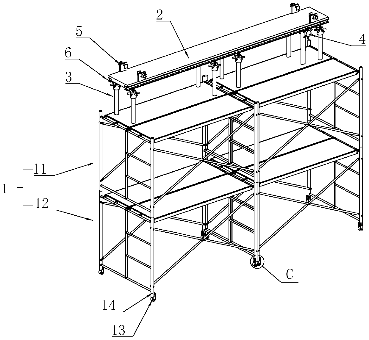
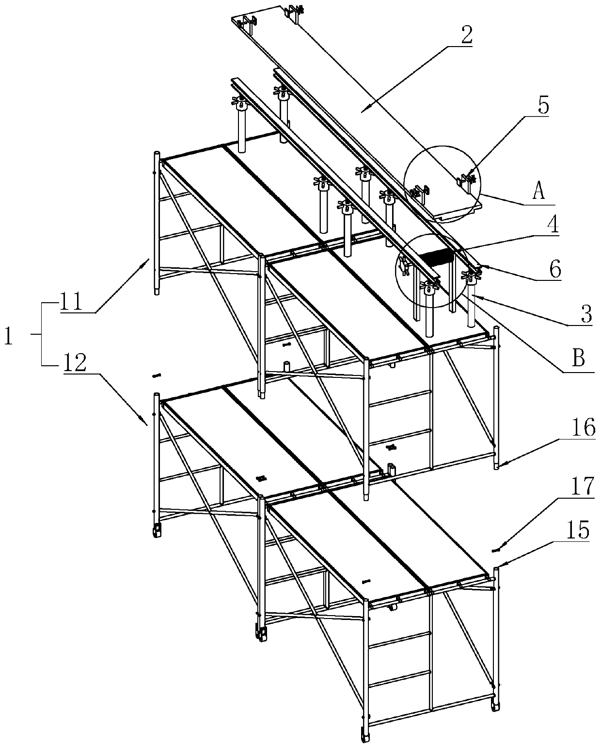
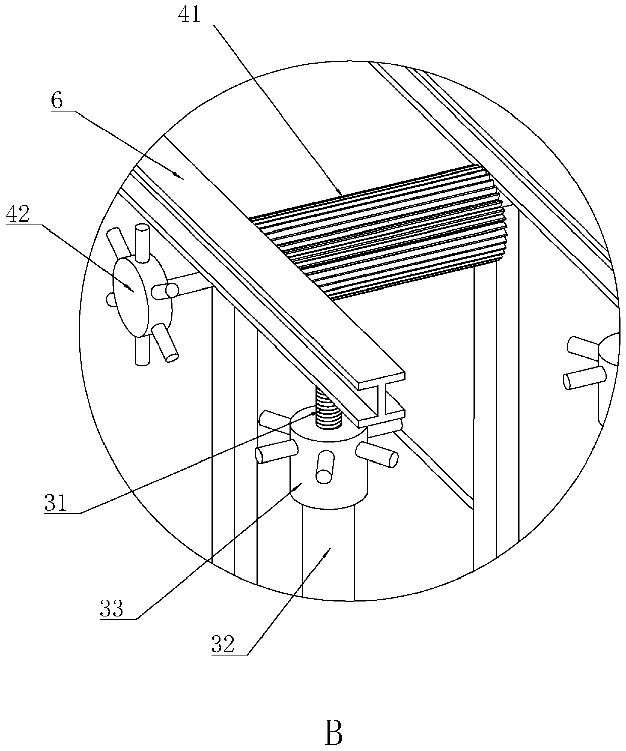
[0048] Embodiment 1: A kind of floor beam mounting bracket, such as figure 1 and figure 2 As shown, it includes a frame body 1, a beam 6, a horizontal adjustment plate 2, a height adjustment mechanism 3, a horizontal adjustment mechanism 4, and a vertical adjustment mechanism 5; wherein there are two beams 6, which are horizontally erected above the frame body 1; height adjustment The mechanism 3 is supported between the frame body 1 and the beam 6 . The horizontal adjustment plate 2 is T-shaped, and the protruding part below it is relatively short. The horizontal adjustment plate 2 is slidably erected on two beams 6, and the lower protrusion is located between the two beams 6 to limit; the horizontal adjustment mechanism 4 is located on the horizontal The bottom of the adjusting plate 2 drives the horizontal adjusting plate 2 to move along the length direction of the beam 6, which is the horizontal direction referred to in this solution. The vertical adjustment mechanism 5...

Embodiment 2

[0054] Embodiment 2: A construction method for using a floor beam mounting bracket, comprising the following steps:

[0055] Step S1 Move the lower frame 12 to the position where the floor beam needs to be installed, turn over the wheel part 13, so that the supporting part 14 of the lower frame 12 touches the ground;

[0056] Step S2 Fix and build one or more upper shelves 11 to a suitable height, and assemble the beam 6 on it, wherein the horizontal adjustment plate 2, the height adjustment mechanism 3, the vertical adjustment mechanism 5, and the height adjustment mechanism 3 mounted on the beam 6 are first Has been assembled on the beam 6;

[0057] Step S3 The tower crane lifts the floor beam to be installed in place and places it on the horizontal adjustment plate 2;

[0058] Step S4 Use the vertical adjustment mechanism 5 to adjust the angle of the floor beam and the position in the width direction of the beam 6;

[0059] Step S5 Utilizes the horizontal adjustment mecha...

Embodiment 3

[0063] Embodiment 3: as Figure 7 As shown, the difference from Embodiment 1 is that the horizontal adjustment plate 2 is respectively provided with a horizontal adjustment mechanism 4 and a reset mechanism 7 on both sides of the width direction at the same length position; The second vertical plate 71 on the plate 2, the spring 72 fixed on the second vertical plate 71 and facing the horizontal adjustment mechanism 4, and the baffle plate 74 fixed on the end of the spring 72, wherein at least one sliding plate is fixed on the inner side of the baffle plate 74 Move through the reset rod 73 of the second vertical plate 71.

[0064] When the bracket is installed and built, setting the horizontal adjustment plate 2 on one side of the bracket in the width direction can reduce the materials for construction, but at this time it also means that only the vertical adjustment mechanism 5 on one side is easy to operate; the spring 72 is used The reset structure can be reversely offset w...


PUM


Abstract

The invention discloses a floor beam mounting bracket and a using construction method. According to the floor beam mounting bracket and the using construction method, the floor beam mounting bracket comprises a bracket body, the top of the bracket body is provided with a crossbeam used for supporting a floor beam and a height adjusting mechanism used for adjusting the height of the crossbeam, andthe crossbeam is provided with a transverse adjusting plate and a transverse adjusting mechanism driving the transverse adjusting plate to move in the length direction of the crossbeam; longitudinal adjusting mechanisms used for adjusting the position of the floor beam in the width direction of the crossbeam are arranged at the two ends or the positions close to the two ends of the transverse adjusting plate in the length direction. According to the mounting bracket, the horizontal position, the angle and the height of the floor beam can be adjusted accurately, the occupancy time of a tower crane and adjustment requirements, for the position of the floor beam, of the tower crane are reduced effectively, and the construction quality of the floor beam is greatly improved on the basis.

Description

technical field [0001] The invention relates to the construction field, in particular to a floor beam installation bracket and a construction method using it. Background technique [0002] At present, among the super high-rise buildings, many buildings adopt the frame-tube structure load-bearing system. The core tube and peripheral frame columns mostly adopt steel concrete structure or ordinary reinforced concrete structure, and its floor structure mostly adopts steel-concrete composite structure. During construction, the connection between the floor beam and the core tube is generally: one end is connected to the corbel on the steel structure, and the other end is connected to the embedded part on the concrete structure (in the case of ordinary reinforced concrete structure). The connection method is generally welding and Bolted together, or used alone. [0003] When the floor beam is connected to the corbel on the steel structure, the connection method is generally a comb...

Claims


Application Information

Patent Timeline
Patent Type & Authority Patents(China)
IPC IPC(8): E04G21/18
CPCE04G21/1841
Inventor 吴寿星林良华陈孝东王筑生陈双敏吴昌伦董文武陈冬伟陈建兰潘建波
Owner 温州威泰建设有限公司
Why Eureka
Try Eureka