Centrifugal fluid equipment and centrifugal impeller used by centrifugal fluid equipment

A technology of fluid equipment and centrifugal impeller, which is applied to mechanical equipment, components of pumping devices for elastic fluids, liquid fuel engines, etc., and can solve the problems of guidance and diffusion, fan diffusion effect and efficiency, etc. Reduce weight, improve diffusion effect and efficiency, and ensure mechanical strength

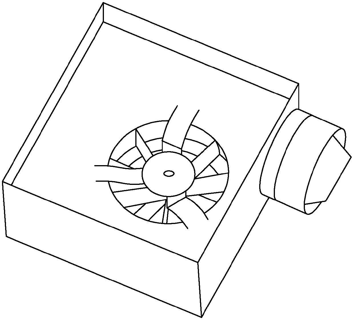
Inactive Publication Date: 2018-03-06
JOHNSON ELECTRIC SHENZHEN
View PDF0 Cites 4 Cited by
  • Summary
  • Abstract
  • Description
  • Claims
  • Application Information

AI Technical Summary

Problems solved by technology

The centrifugal fan adopts a centrifugal impeller with straight blades. Since the centrifugal impeller with straight blades cannot guide and diffuse the wind well, the diffusion effect and efficiency of the fan are not ideal.

Method used


Image

  • Centrifugal fluid equipment and centrifugal impeller used by centrifugal fluid equipment
  • Centrifugal fluid equipment and centrifugal impeller used by centrifugal fluid equipment
  • Centrifugal fluid equipment and centrifugal impeller used by centrifugal fluid equipment

Examples


Embodiment Construction

[0046] Various embodiments of the present invention will be described with reference to the accompanying drawings. It can be understood that the drawings are only used for reference and description, and are not intended to limit the present invention. The dimensions shown in the drawings are only for the convenience of clear description, and do not limit the proportional relationship or give an exhaustive description of the present invention, nor limit the scope of the present invention. The described embodiments are only some, not all, embodiments of the present invention. Based on the embodiments of the present invention, all other embodiments obtained by persons of ordinary skill in the art without making creative efforts belong to the protection scope of the present invention. Unless otherwise defined, all technical and scientific terms used herein have the same meaning as commonly understood by one of ordinary skill in the technical field of the invention.

[0047] see ...


PUM


Abstract

A centrifugal fluid device and the impeller used therein, the impeller includes a plurality of blades, the blades are backward-curved blades, the starting ends of some or all of the blades are located on a circle with the impeller shaft as the axis and a diameter of D1 , the ends of all the blades are located on a circle with the impeller shaft as the axis and a diameter of D2, wherein, the D1 / D2=0.5~0.6; the inlet angle of the inner flow channel of each blade is formed at the beginning of each blade , the inlet angle is the angle between the outer extension line of the blade passing the starting end and the radius of the circle with a diameter D1 passing the starting end, and the value of the inlet angle is 60° to 80°; each of the blades The outlet angle of the inner flow channel of the blade is formed at the end, and the outlet angle is the angle between the outer extension line of the blade passing through the end and the tangent line of a circle with a diameter of D2 passing through the end and following the direction of impeller rotation. The value is from 165° to 175°. The invention can effectively improve the diffusion effect and efficiency of the centrifugal fluid equipment.

Description

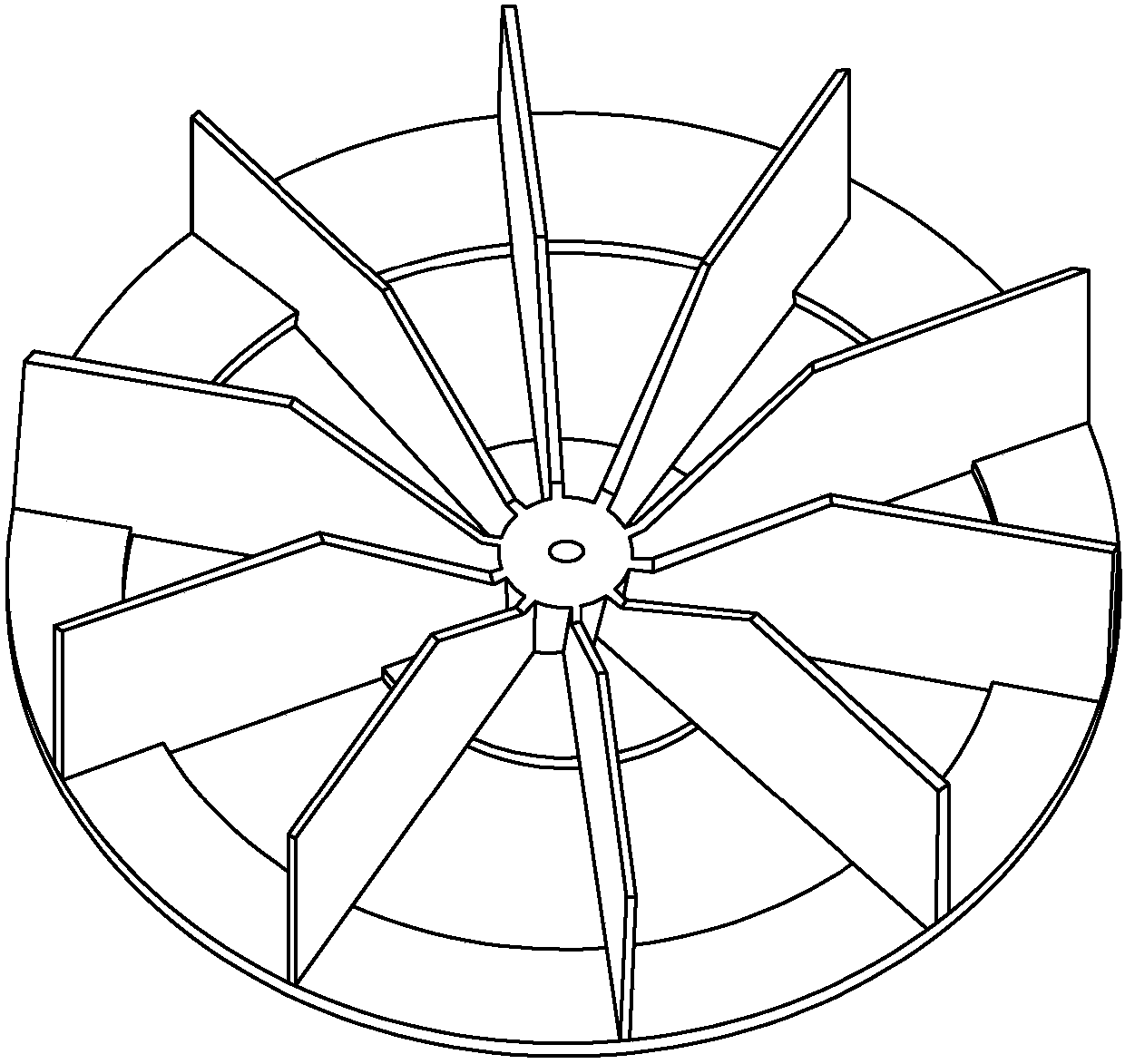
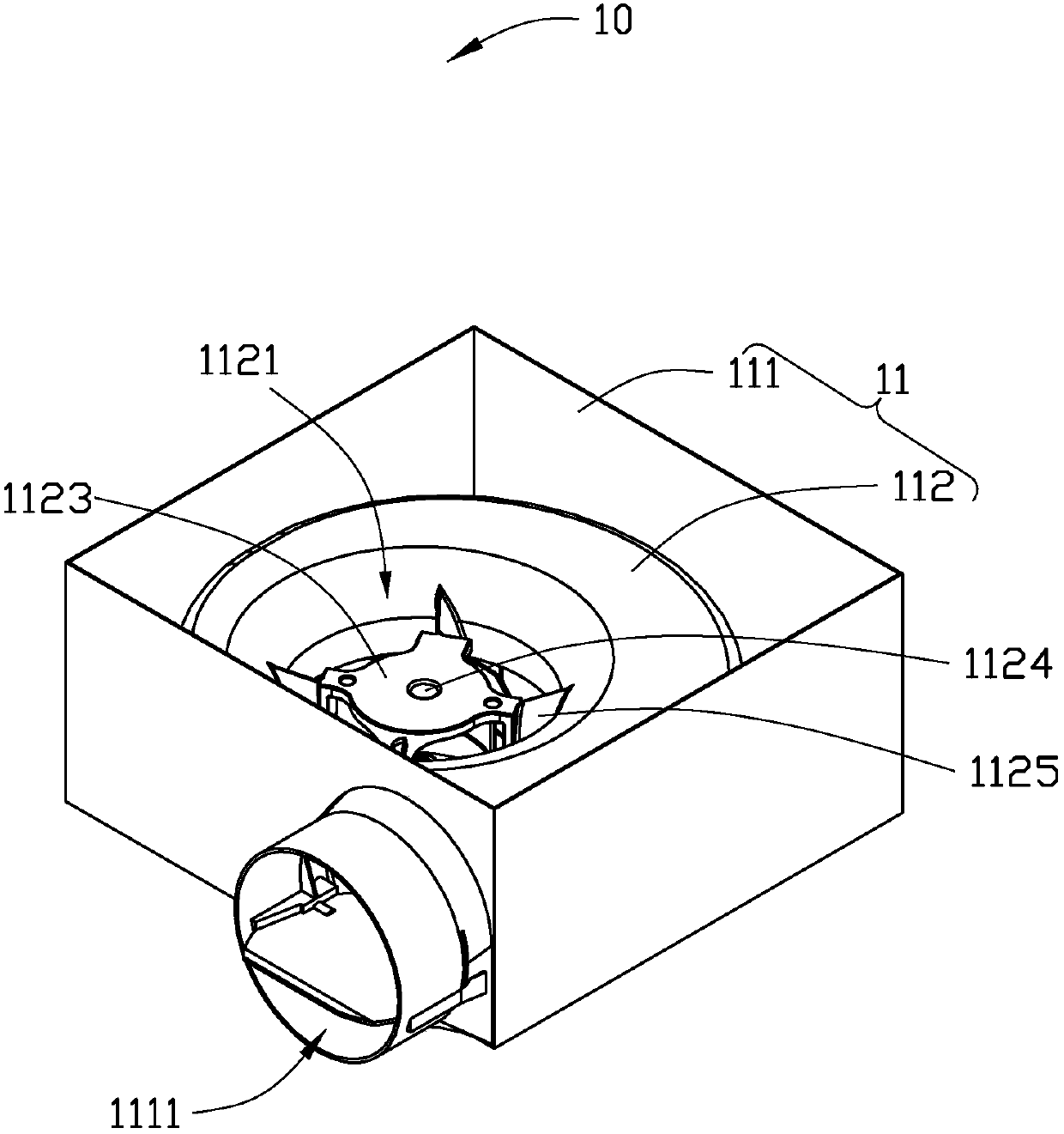
【Technical field】 [0001] The present invention relates to the improvement of centrifugal fluid equipment such as ventilator, blower, especially relates to the improvement of impeller and casing used in centrifugal fluid equipment. 【Background technique】 [0002] see figure 1 and figure 2 Shown, be existing a kind of centrifugal fan. The centrifugal fan adopts a centrifugal impeller with straight blades. Since the centrifugal impeller with straight blades cannot guide and diffuse the wind well, the diffusion effect and efficiency of the fan are not ideal. [0003] Therefore, it is necessary to improve the existing centrifugal fan and the centrifugal impeller used to improve its diffusion effect and efficiency. 【Content of invention】 [0004] The object of the present invention is to provide a centrifugal fluid device with improved diffusion effect and efficiency. To this end, the centrifugal fluid equipment provided by the present invention includes a casing and an imp...

Claims


Application Information

Patent Timeline
IPC IPC(8): F04D29/30F04D29/28
CPCF04D29/30F04D29/281
Inventor 方传慧李红光张小良
Owner JOHNSON ELECTRIC SHENZHEN
Why Eureka
Try Eureka