Light projection measurement device and method for axial clearance of movable and stationary blades of engine

A technology of axial clearance and measurement method, applied in mechanical measurement devices, measurement devices, optical devices, etc., to achieve the effect of low intervention and high measurement accuracy

Pending Publication Date: 2018-03-06
TIANJIN UNIV
View PDF5 Cites 10 Cited by
  • Summary
  • Abstract
  • Description
  • Claims
  • Application Information

AI Technical Summary

Problems solved by technology

[0003] There is no mature technology in the field of real-time dynamic detection of the axial clearance of moving and static blades in China. In order to adapt to the development of "high power, high thrust, and low energy consumption" of engines in the new era, it will further fill the gap in the domestic engine detection field and realize multi-dimensional, all-round In terms of detection, a measurement method and measurement system for the axial clearance of large rotating machinery moving and stationary blades need to be studied

Method used


Image

  • Light projection measurement device and method for axial clearance of movable and stationary blades of engine
  • Light projection measurement device and method for axial clearance of movable and stationary blades of engine
  • Light projection measurement device and method for axial clearance of movable and stationary blades of engine

Examples


Embodiment Construction

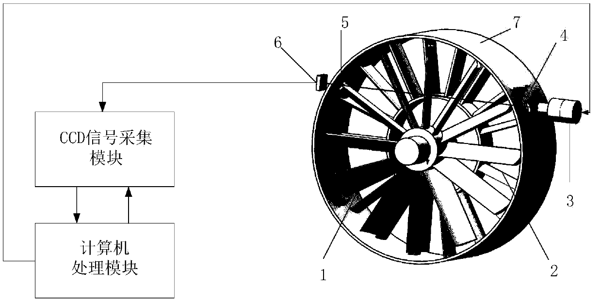
[0021] The technical scheme adopted by the present invention is an axial measurement system for moving and stationary blades of an engine based on the light projection method, the schematic diagram of the system is shown in figure 1 . The system includes the following modules:

[0022] Optical path system module: This module requires a strong parallel white light source with a divergence angle of less than 1° and uniform distribution of light intensity. The size of the light spot is larger than the size of the casing opening, and the diameter of the casing opening is also larger than the gap between the moving blade and the stationary blade. As well as the range of variation, a suitable lens group or lens makes the light spot image on the line array / area array CCD surface of the photoelectric sensor device.

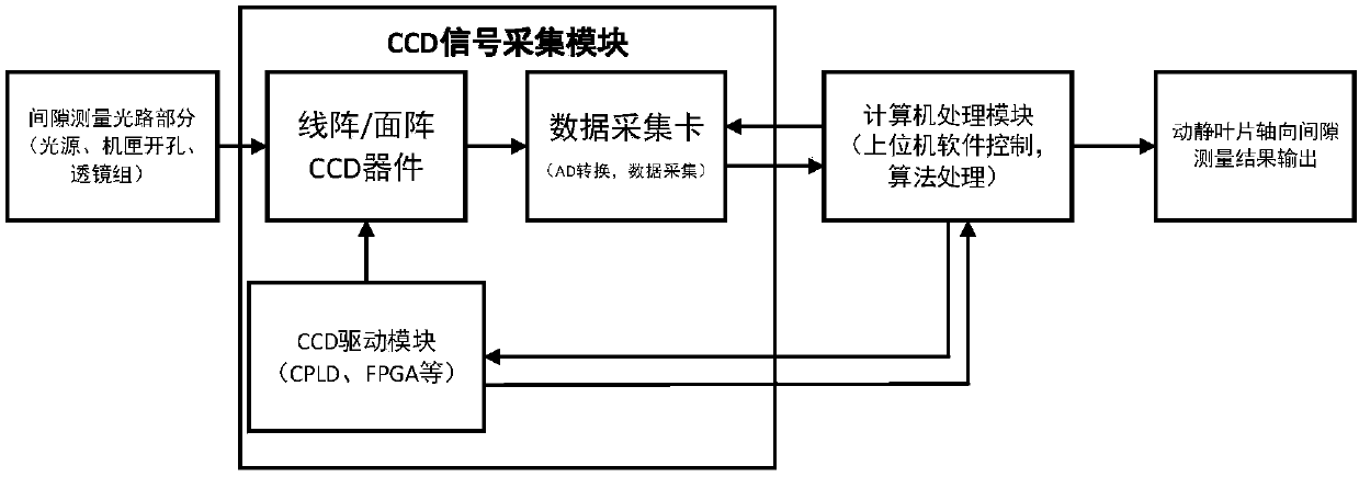
[0023] Area array / linear array CCD signal acquisition module: This module includes area array or linear array CCD sensor, CCD signal drive module (can be driven by CPLD,...


PUM


Abstract

The invention belongs to the field of engine detection, and relates to a light projection measurement device and method which can realize real-time dynamic measurement for the axial clearance of movable and stationary blades of an engine through applying an optical path system designed in allusion o actual conditions and a subsequent signal processing module. The technical scheme of the inventionis that the light projection measurement device for the axial clearance of the movable and stationary blades of the engine structurally comprises an optical path system module, an area array / linear array CCD signal acquisition module and a computer processing module, wherein the optical path system module a strong parallel white light source with the divergence angle being less than 1 degree, andthe light intensity of the strong parallel white light source is uniformly distributed; the area array / linear array CCD signal acquisition module comprises an area array or linear array CCD sensor, aCCD signal driving module and a signal acquisition module, and enables a light spot to be projected to a linear array or area array CCD by being matched with a lens with appropriate parameters; and the computer processing module is used for controlling acquisition for axial clearance signals of the movable and stationary blades, processing the acquired signals to obtain a clearance measurement value and performing analysis, storage and display on the data according to requirements. The light projection measurement device and method are mainly applied to occasions of engine detection.

Description

technical field [0001] The invention belongs to the field of engine detection, and relates to a method capable of on-line measurement of the axial clearance of large mechanical dynamic and stationary blades. Specifically, it relates to a light projection measurement method for axial clearance measurement of moving and stationary blades of an engine. Background technique [0002] In large-scale rotating machinery such as aero-engines, gas turbines, steam turbines, and flue gas turbines, blades are the core components, and their operating state parameters directly affect the working performance and operation safety of the equipment. Traditional blade detection mainly focuses on the rotating blades of large-scale rotating machinery. Measurement of tip clearance and blade vibration. With the continuous iteration of engine models, especially the continuous improvement of turbine engine power, after entering the 1990s, engines with a thrust-to-weight ratio of 10.0 have been widel...

Claims


Application Information

Patent Timeline
Patent Type & Authority Applications(China)
IPC IPC(8): G01B11/14
CPCG01B5/003G01B11/14
Inventor 段发阶郑好程仲海蒋佳佳
Owner TIANJIN UNIV
Why Eureka
Try Eureka