
Particle-reinforced composite-material finite-element modeling method of considering microstructure interface

A composite material and microstructure technology, applied in special data processing applications, instruments, electrical digital data processing, etc., can solve problems such as low modeling efficiency, inability to accurately reflect the real microstructure of materials, and complicated operations

Active Publication Date: 2018-03-06
BEIJING INSTITUTE OF TECHNOLOGYGY
View PDF8 Cites 16 Cited by
  • Summary
  • Abstract
  • Description
  • Claims
  • Application Information

AI Technical Summary

Problems solved by technology

[0006] In order to establish a finite element model of particle-reinforced composite materials more accurately, the existing modeling problems such as low efficiency, complicated operation, and inability to accurately reflect the real microstructure of the material should be changed.
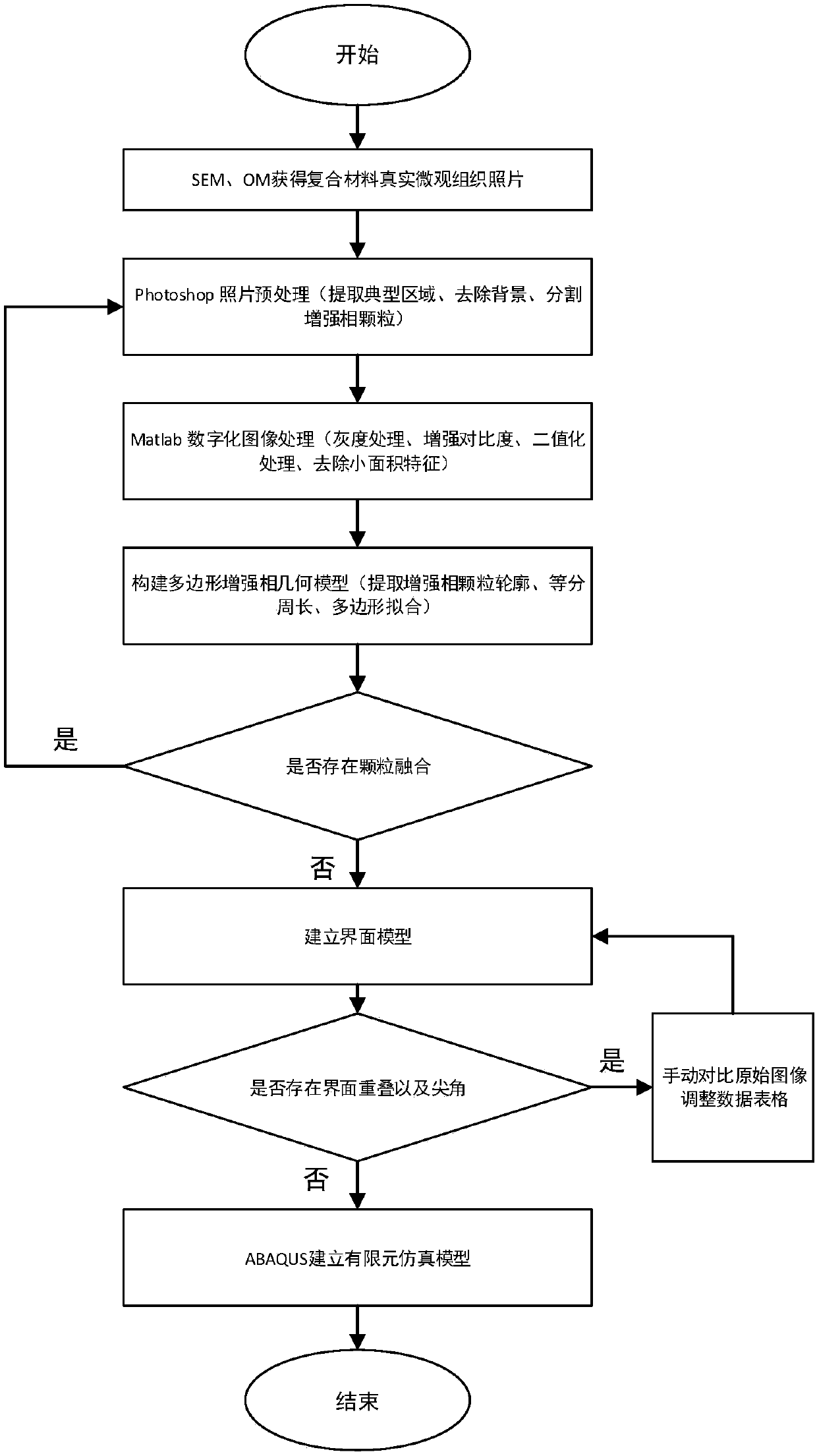
The technical problem to be solved by the finite element modeling method of particle-reinforced composite material considering microstructure interface disclosed by the present invention is to provide a finite element modeling method combining various digital image processing software and finite element simulation software, considering The influence of the microstructure interface on the finite element model of particle-reinforced composite materials improves the simulation accuracy and reliability of the finite element model of particle-reinforced composite materials, and then solves engineering problems in the field of particle-reinforced composite materials. It has simplified digital image processing and finite element software modeling The advantage of complexity

Method used


Image

  • Particle-reinforced composite-material finite-element modeling method of considering microstructure interface
  • Particle-reinforced composite-material finite-element modeling method of considering microstructure interface
  • Particle-reinforced composite-material finite-element modeling method of considering microstructure interface

Examples


Embodiment 1

[0178] The finite element modeling method of particle reinforced composite materials disclosed in this embodiment considering the microstructure interface, the specific implementation method is as follows:

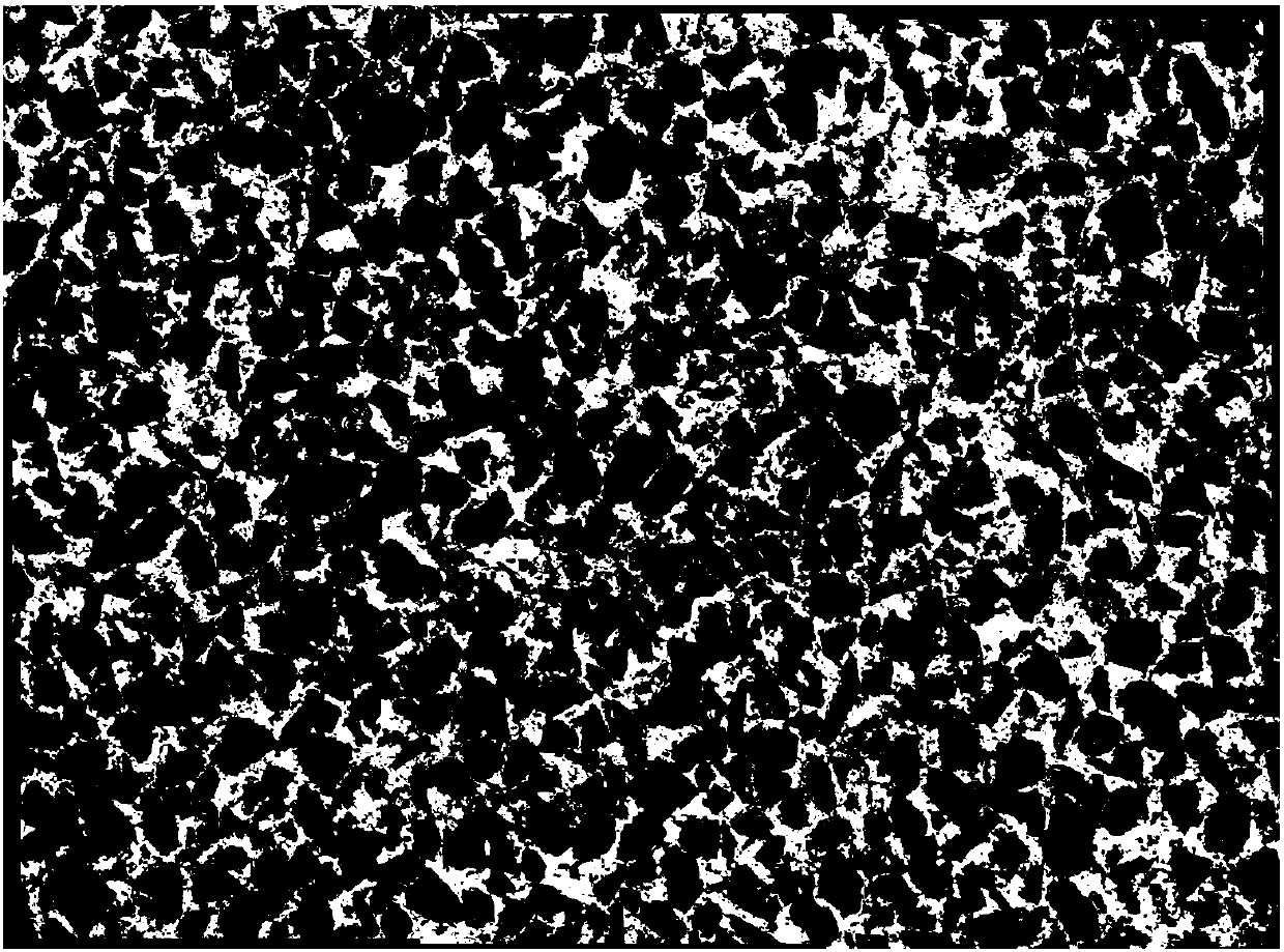
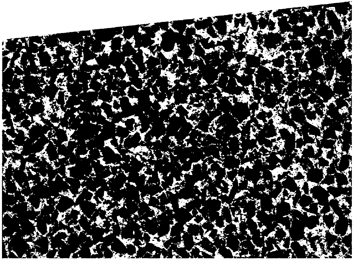
[0179] Step 1. Use the Keyence laser scanning microscope to obtain a digital image of the microstructure of the particle-reinforced composite material SiCp / Al, and save it in JPEG format, such as figure 2 ;

[0180] For the SiCp / Al material used, the cross-section of the material is obtained after wire cutting, grinding, and polishing processes, and the oxidation and corrosion areas on the surface of the material are effectively removed, and the microstructure of the material is extracted using a KEYENCE laser scanning microscope , to obtain optical microscope images of the microstructure of the studied particle-reinforced composites.

[0181] Step 2: Use Photoshop to preprocess the original photos.

[0182]Use the cropping function of Photoshop to remove the black bord...


PUM


Abstract

The invention discloses a particle-reinforced composite-material finite-element modeling method of considering a microstructure interface, relates to a composite-material finite-element modeling method, and belongs to the field of particle-reinforced composite materials. According to the method, a deviation method is used to establish a geometric model of the reinforced-phase particle interface onthe basis of definition of traditional particle-reinforced composite-material finite-element models on geometric modeling, materials and contact of a matrix and reinforced-phase particles, consideration of influences of the microstructure interface on a particle-reinforced composite-material finite-element model is realized through carrying out assignment of material and contact attributes to thereinforced-phase particle interface, accuracy and reliability of particle-reinforced composite-material finite-element model simulation are improved, and then engineering problems of the particle-reinforced composite-material field are solved. In addition, the method has the advantage of simplifying complexity of digital image processing and finite-element software modeling. The method is suitable for, but not limited to, finite-element modeling of particle-reinforced composite materials.

Description

technical field [0001] The invention relates to a finite element modeling method for composite materials, in particular to a finite element modeling method for particle-reinforced composite materials considering microstructure interfaces, and belongs to the field of particle-reinforced composite materials. Background technique [0002] Particle-reinforced metal matrix composites have the characteristics of high strength, high elastic modulus, wear resistance, and good electrical and thermal conductivity. They are widely used in aerospace, electronics, automobiles, and construction industries. In exploring the performance of materials, we often use the method of finite element modeling. The microstructure of metal matrix composites, such as particle morphology, size, distribution, content and interface properties, has a very important impact on the overall performance of composite materials. , therefore, how to establish a finite element model that is close to reality is extr...

Claims


Application Information

Patent Timeline
IPC IPC(8): G06F17/50
CPCG06F30/23
Inventor 解丽静高飞农项俊锋程冠华胡鑫王涛王西彬
Owner BEIJING INSTITUTE OF TECHNOLOGYGY
Learn More