Outdoor energy-saving power distribution box

A distribution box and box technology, which is applied in the substation/distribution device casing, electrical components, substation/switch layout details, etc., can solve the problem of high energy consumption, reduce energy consumption, achieve blocking effect, and reduce the way Effect

Inactive Publication Date: 2018-03-06
四川东大恒泰电气有限责任公司
View PDF4 Cites 2 Cited by
  • Summary
  • Abstract
  • Description
  • Claims
  • Application Information

AI Technical Summary

Problems solved by technology

[0009] In order to solve the problem of high energy consumption in the existing power distribution box through the heat dissipation fan, the present invention provides an outdoor energy-saving power distribution box, which can meet the heat dissipation requirements of the power distribution box without using a heat dissipation fan

Method used


Image

  • Outdoor energy-saving power distribution box
  • Outdoor energy-saving power distribution box
  • Outdoor energy-saving power distribution box

Examples


Embodiment 1

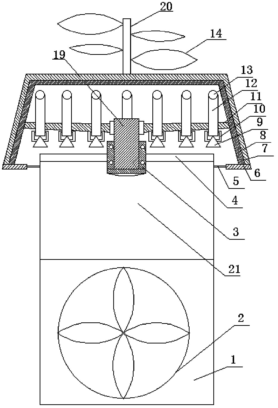
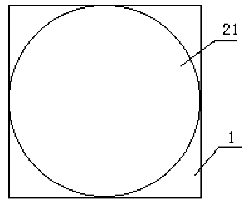
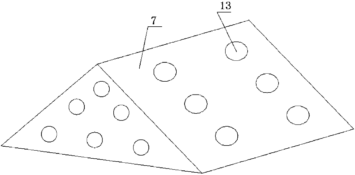
[0045] Such as Figure 1-4 , an outdoor energy-saving distribution box in this embodiment, comprising a box body, the lower part 1 of the box body has a rectangular cross section, the upper part 21 of the box body has a circular cross section, and a support frame is provided at the upper end of the box body 4. A bearing seat 3 is provided at the center of the support frame 4, and a rotating shaft 19 is set inside the bearing seat 3. The upper end of the rotating shaft 19 is connected to a ceiling, and the ceiling includes a bracket 11 and a side plate 7. The side plate 7 is connected on the support 11 in the shape of a "herringbone", and several air pipes are arranged on the side plate 7, and the air pipes include a first air pipe 13 and a second air pipe 12. The air pipe 13 is arranged on the side plate 7 obliquely upwards, the second air pipe 12 is arranged along the vertical direction, and the first air pipe 13 and the second air pipe 12 are communicated; the upper end of t...

Embodiment 2

[0047] Such as Figure 1-4 , an outdoor energy-saving distribution box in this embodiment, comprising a box body, the lower part 1 of the box body has a rectangular cross section, the upper part 21 of the box body has a circular cross section, and a support frame is provided at the upper end of the box body 4. A bearing seat 3 is provided at the center of the support frame 4, and a rotating shaft 19 is set inside the bearing seat 3. The upper end of the rotating shaft 19 is connected to a ceiling, and the ceiling includes a bracket 11 and a side plate 7. The side plate 7 is connected on the support 11 in the shape of a "herringbone", and several air pipes are arranged on the side plate 7, and the air pipes include a first air pipe 13 and a second air pipe 12. The air pipe 13 is arranged on the side plate 7 obliquely upwards, the second air pipe 12 is arranged along the vertical direction, and the first air pipe 13 and the second air pipe 12 are communicated; the upper end of t...

Embodiment 3

[0049] Such as Figure 1-4 , an outdoor energy-saving distribution box in this embodiment, comprising a box body, the lower part 1 of the box body has a rectangular cross section, the upper part 21 of the box body has a circular cross section, and a support frame is provided at the upper end of the box body 4. A bearing seat 3 is provided at the center of the support frame 4, and a rotating shaft 19 is sleeved inside the bearing seat 3. The upper end of the rotating shaft 19 is connected to a ceiling, and the ceiling includes a bracket 11 and a side plate 7. The side The plate 7 is connected to the support 11 in the shape of a "herringbone", and several air pipes are arranged on the side plate 7, and the air pipes include a first air pipe 13 and a second air pipe 12. The air pipe 13 is arranged on the side plate 7 obliquely upwards, the second air pipe 12 is arranged along the vertical direction, the first air pipe 13 communicates with the second air pipe 12; the upper end of ...


PUM


Abstract

The invention belongs to the technical field of distribution boxes, and discloses an outdoor energy-saving distribution box, which is used to solve the problem of high energy consumption in the existing distribution box through cooling fans. Including the box body, the lower cross section of the box body is rectangular, the upper cross section of the box body is circular, the upper end of the box body is provided with a support frame, the center of the support frame is provided with a bearing seat, and the shown bearing seat is sleeved There is a rotating shaft, and the upper end of the rotating shaft is connected with a ceiling, and the ceiling includes a bracket and a side plate, and the side plate is connected to the bracket in a “herringbone” shape, and several ventilation pipes are arranged on the side plate, so The ventilation pipe includes a first ventilation pipe and a second ventilation pipe, the first ventilation pipe is arranged on the side plate obliquely upward, the second ventilation pipe is arranged along the vertical direction, the first ventilation pipe and the second ventilation pipe The two ventilation pipes are connected; the upper end of the ceiling is connected with a windshield device for driving the ceiling to rotate on the bearing seat, and the lower part of the box is provided with a ventilation fan.

Description

technical field [0001] The invention belongs to the technical field of distribution boxes, and in particular relates to an outdoor energy-saving distribution box. Background technique [0002] Distribution box generally constitutes a low-voltage distribution box. According to electrical wiring, it is required to be assembled in closed or semiclosed metal safe by switchgear, measuring instrument, protective device and auxiliary equipment or on the screen width, forms low-voltage distribution box. During normal operation, the circuit can be connected or disconnected by means of a manual or automatic switch. [0003] There are also many technical documents about distribution boxes in the prior art. For example, the patent application number 201620679235.2 discloses an electric automation distribution box, including a box body. The box door at the front of the main body and the base at the bottom of the main body of the cabinet are composed of a ventilation device on the left s...

Claims


Application Information

Patent Timeline
Patent Type & Authority Applications(China)
IPC IPC(8): H02B1/46H02B1/28H02B1/56
CPCH02B1/46H02B1/28H02B1/565
Inventor 张文滔
Owner 四川东大恒泰电气有限责任公司
Why Eureka
Try Eureka