An Improved Push-Pull Converter Based on Sliding Mode Control

A converter and sliding mode technology, applied in control/regulation systems, output power conversion devices, DC power input conversion to DC power output, etc., can solve the problem that the dynamic response of the push-pull circuit cannot be improved, and the push-pull circuit is robust Insufficient performance, stability and dynamic quality, complex parameters and other problems, to achieve the effect of simple design, good stability and good robustness

Active Publication Date: 2019-12-31
SHAANXI AVIATION ELECTRICAL
View PDF4 Cites 0 Cited by
  • Summary
  • Abstract
  • Description
  • Claims
  • Application Information

AI Technical Summary

Problems solved by technology

At present, the push-pull circuit is mainly controlled by the traditional PID control method, but when the traditional PID control method improves the system stability, the parameter setting is more complicated, often depends on certain engineering experience, and cannot improve the existing PWM voltage and PWM The dynamic response problem of the push-pull circuit in the current control mode leads to the shortcomings of the current push-pull circuit in terms of system robustness, stability and dynamic quality

Method used


Image

  • An Improved Push-Pull Converter Based on Sliding Mode Control
  • An Improved Push-Pull Converter Based on Sliding Mode Control
  • An Improved Push-Pull Converter Based on Sliding Mode Control

Examples


Embodiment Construction

[0029] Embodiments of the present invention are described in detail below, and the embodiments are exemplary and intended to explain the present invention, but should not be construed as limiting the present invention.

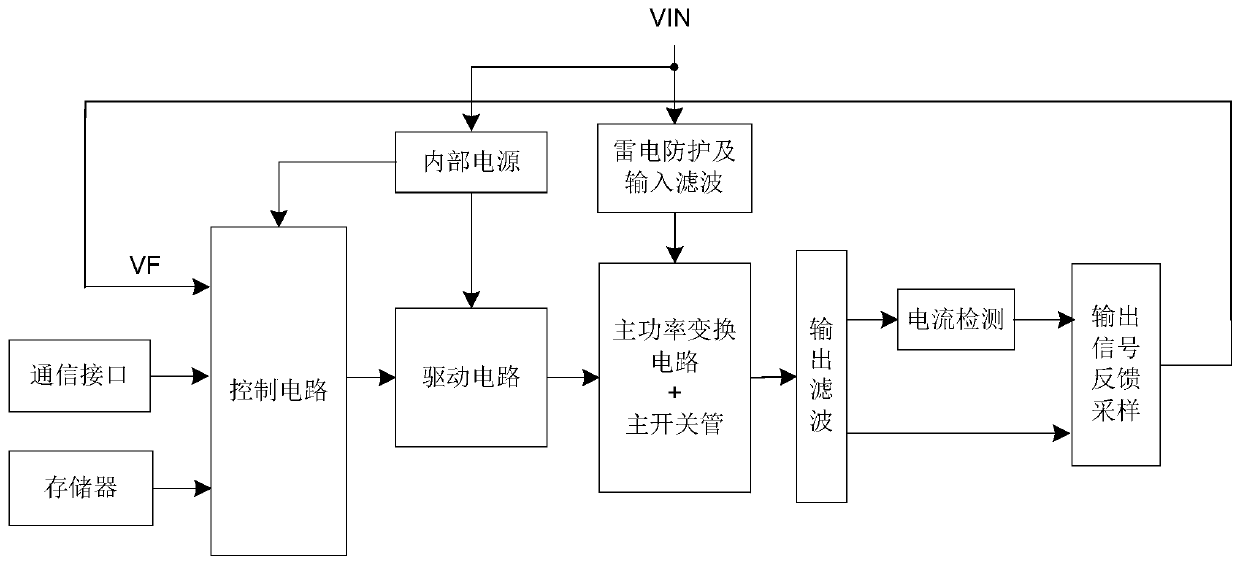
[0030] Such as figure 1 As shown, a new type of push-pull converter based on sliding mode control in this embodiment includes lightning protection and input filter circuit, internal power supply, control circuit, drive circuit, main power conversion circuit and primary switch tube, output filter circuit , a current detection unit, and an output signal feedback sampling circuit.

[0031] The external DC input power supply is connected to the lightning protection and input filter circuit and the internal power supply, and the internal power supply supplies power to the control circuit and the drive circuit; the output end of the lightning protection and input filter circuit is connected to the main power conversion circuit and the primary switch tube, so The ma...


PUM


Abstract

The invention provides an improved push-pull converter based on sliding mode control. The push-pull converter is improved on the basis of an original push-pull circuit. DC input voltage is directly imported to the midpoint of the secondary side of a transformer and is used to increase the secondary voltage of the transformer. Thus, the product output voltage is the sum of the input voltage and theconversion voltage of a power conversion circuit. The power conversion circuit only provides the difference between the input voltage and the output voltage. Such topology can significantly improve the efficiency of a product. In addition, the system uses voltage-current double loop control based on a sliding mode control algorithm, and designs a sliding mode surface according to desired dynamiccharacteristics. By designing a sliding mode control law, a controlled system converges along the sliding mode surface. Thus, good robustness, stability and dynamic quality of the system are guaranteed.

Description

technical field [0001] The invention relates to the field of power electronics, in particular to an improved push-pull converter based on sliding mode control for aviation, which is mainly suitable for conversion devices with low input and output voltage ranges. Background technique [0002] With the rapid development of power electronics technology, the aviation power system has gradually entered the era of multi-electricity and all-electricity. The multi-electric system is the core technology of the multi-electric aircraft. Compared with the traditional system, its secondary power system is controlled and distributed in the form of electric energy. As the link between the power generation system and the load, the secondary power supply is the basis of the multi-electric system and the multi-electric aircraft, and its performance directly affects the reliability of the entire on-board power generation system. Considering the working environment and working conditions of th...

Claims


Application Information

Patent Timeline
Patent Type & Authority Patents(China)
IPC IPC(8): H02M3/337
CPCH02M3/3376
Inventor 胡锦房磊仝倩黄鸿李真贵
Owner SHAANXI AVIATION ELECTRICAL
Why Eureka
Try Eureka