Rotary positioning system for steel pipe pole of power transmission line
A transmission line steel pipe and positioning system technology, which is applied in the field of transmission line steel pipe pole rotation positioning system, can solve the problems of poor rotation precision of rods and constant length adjustment, and achieves a high degree of automation, saving labor costs, and high transmission precision. Effect
- Summary
- Abstract
- Description
- Claims
- Application Information
AI Technical Summary
Problems solved by technology
Method used
Image
Examples
Embodiment 1
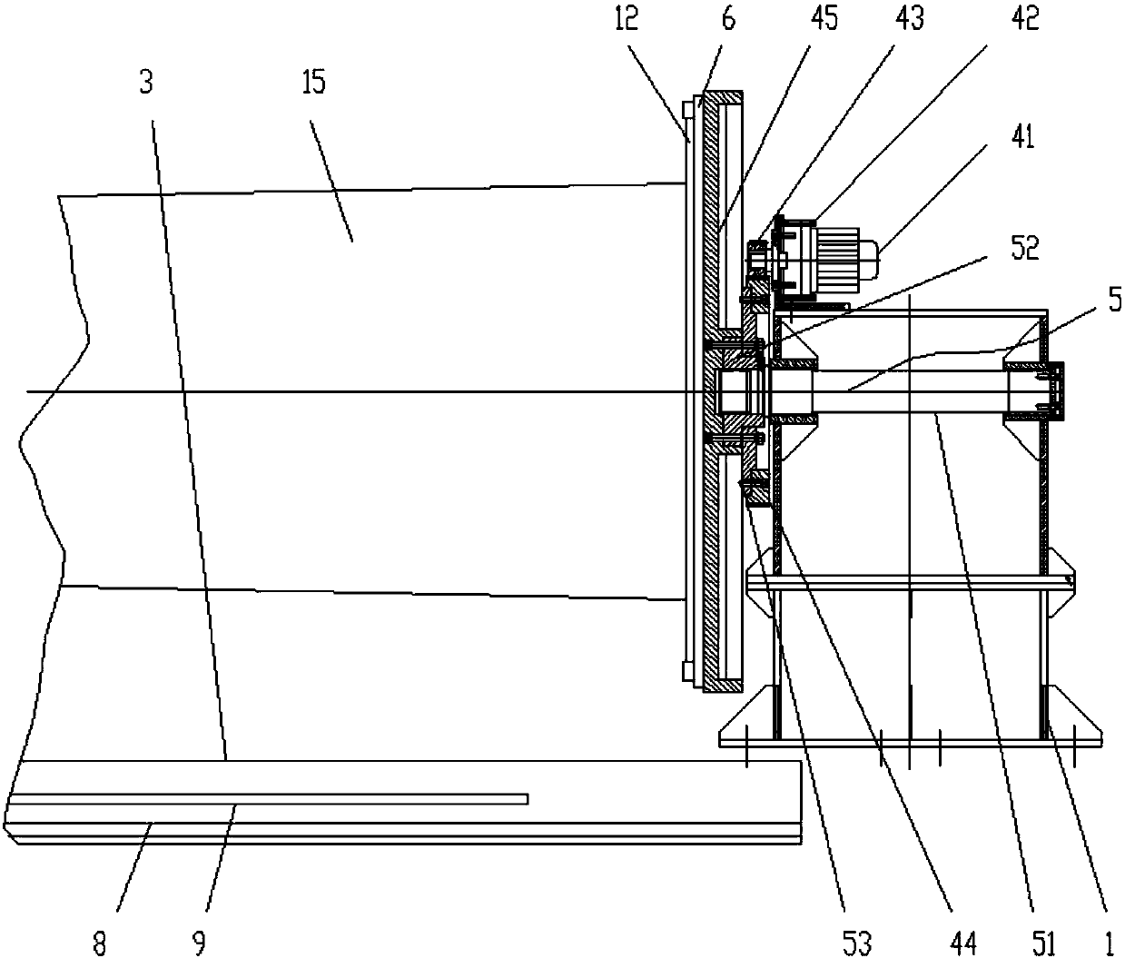
[0029] Such as Figure 1 to Figure 4 As shown, a steel pipe rod rotation positioning system for transmission lines includes a driving end 1, a tailstock 2 and an underframe 3, the driving end 1 is equipped with a rotating power head 4 for fixing the tail of a steel pipe rod 15, and the underframe The side of 3 is provided with guide rail 8, and described tailstock 2 is slidably connected on the guide rail 8 by slide block 19, and described slide block 19 is provided with tailstock positioning mechanism, and both on described rotary power machine head 4 and tailstock 2 A four-jaw chuck 6 is installed. The four-jaw chuck 6 is used to clamp the flange 12 or the steel pipe rod 15 to facilitate the alignment welding of the steel pipe rod 15 in the later stage.
[0030] It is worth noting that the rotary power head 4 includes a servo motor 41, a reducer 42, a driving gear 43, a driven gear 44 and a chuck base 45, and the servo motor 41 is installed on the top of the driving end 1, ...
Embodiment 2
[0036] Such as Figure 5 As shown, in order to facilitate the welding of the steel pipe rod 15, on the basis of Embodiment 1, a walking robot 16 is also arranged on the guide rail 8, and the walking robot 16 includes a machine base 161, a welding bracket 162 and a welding head 163, the inner side of the base 161 is provided with a chute that cooperates with the guide rail 8, the base 161 is slidably connected with the guide rail 8 through the chute, the welding bracket 162 is installed on the top of the base 161 by bolts, the welding The head 163 is disposed on the top of the welding bracket 162 .
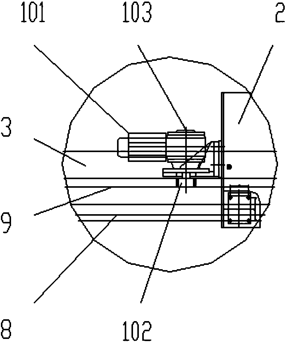
[0037] In this embodiment, in order to realize the automatic walking of the walking robot 16, a drive mechanism is installed on the side of the base 161. The drive mechanism includes a drive motor 17 using a servo motor 41 and a drive gear 108. The drive motor 17 is connected with drive gear 108 shafts, and drive gear 108 is meshedly connected with rack 9.
Embodiment 3
[0039] Such as Figure 6 As shown, if only in order to realize the rotary positioning and welding work of the rib plate 11 on one end of the steel pipe rod 15, on the basis of embodiment 2, the tailstock 2 part can be removed, and the driving end 1 and the rotating power head 4 can be used Realize the rotation of the steel pipe rod 15 and the flange 12, after fixing the rib plate 11 at an appropriate position, use the welding head 163 provided on the walking robot 16 to carry out the welding work, thereby welding several rib plates 11 on the outer ring of the steel pipe rod 15 , improve the stability of the connection between the steel pipe rod 15 and the flange 12 .
PUM
 Abstract
Description
Claims
Application Information
 - R&D
- Intellectual Property
- Life Sciences
- Materials
- Tech Scout
- Unparalleled Data Quality
- Higher Quality Content
- 60% Fewer Hallucinations
Browse by: Latest US Patents, China's latest patents, Technical Efficacy Thesaurus, Application Domain, Technology Topic, Popular Technical Reports.
© 2025 PatSnap. All rights reserved.Legal|Privacy policy|Modern Slavery Act Transparency Statement|Sitemap|About US| Contact US: help@patsnap.com


