Cable external-screen stripper

A cable and head stripping technology, used in cable installation, cable installation devices, equipment for dismantling/armored cables, etc. Simple structure, improved peeling and cutting precision, and the effect of improving precision

Pending Publication Date: 2018-03-09
张同义
View PDF0 Cites 9 Cited by
  • Summary
  • Abstract
  • Description
  • Claims
  • Application Information

AI Technical Summary

Problems solved by technology

However, the cable positioning assembly in the cutting device of the cable outer shielding layer in the prior art only clamps one surface of the cable. When the cutting tool is cutting, the cable is easy to deviate and difficult to grasp, so the cutting accuracy is not high, and the cutting stroke The length is not enough to meet the requirements of the partial discharge test; secondly, the positioning component structure of the outer shielding layer of the cable is more complicated, including clamps, rulers and laser positioners, and the required cost is relatively high, because this device is not positioned. It is too cumbersome to use, which is not conducive to popularizing applications

Method used


Image

  • Cable external-screen stripper
  • Cable external-screen stripper
  • Cable external-screen stripper

Examples


Embodiment 1

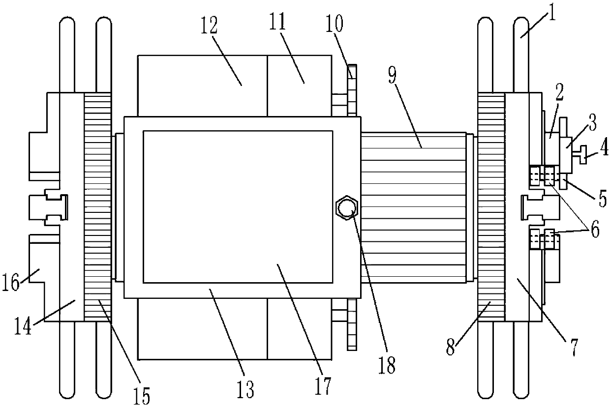
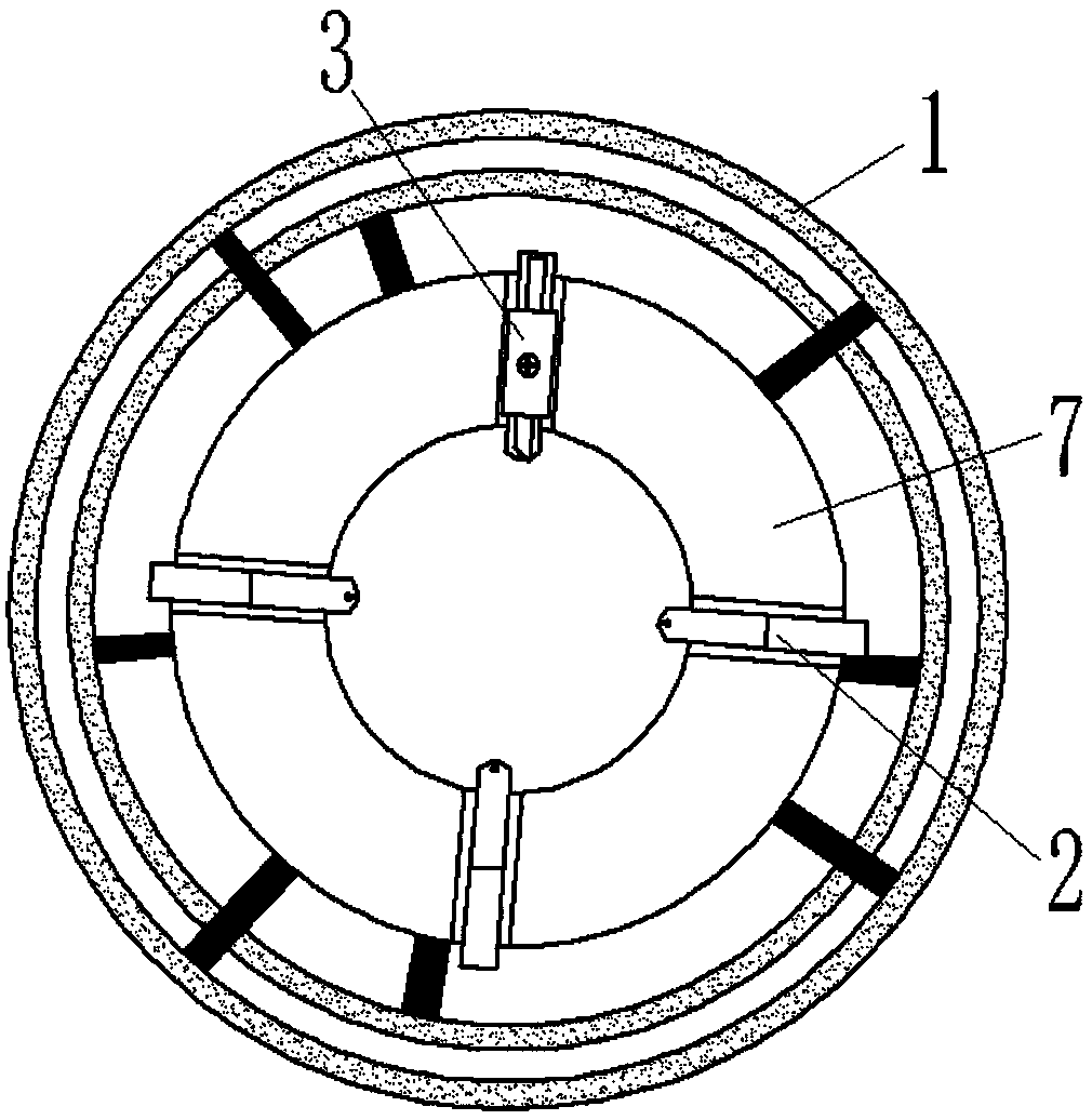
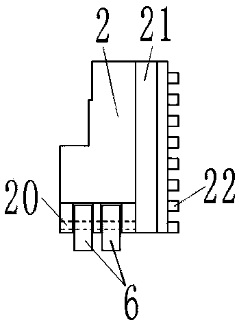
[0025] Such as Figure 1-7 As shown, a cable outer screen stripping device includes a housing 13, a transmission device, a cutter assembly, a movable stripping chuck 7 and a fixed chuck 14, and the fixed chuck 14 is fixedly connected to one end of the housing 13; the transmission device One end is connected in the other end of the housing 13 and can rotate relative to the housing 13, and the dynamic peeling chuck 7 is fixedly connected to the other end of the transmission device; the end of the transmission device connected in the housing 13 is connected with the housing 13 threads; 13. The transmission device, the fixed chuck 14 and the dynamic stripping chuck 7 are coaxially arranged, and holes for cables to pass through are respectively provided inside; the fixed chuck 14 and the dynamic stripping chuck 7 are also equipped with cable clamping and positioning components , the cable clamping and positioning assembly includes a fixed chuck push plate 15, a dynamic stripping ch...

Embodiment 2

[0032] Embodiment 2 is another structure of the transmission device, such as Figure 8 As shown, a transmission device of a cable outer screen stripper includes a hollow shaft 29, a rotating cylinder 31, a stator 32 and a rotor 33, the stator 32 is annular and is arranged on the inner wall of the housing 13, and the stator 31 is wound with a stator coil The rotating cylinder 31 is arranged coaxially with the housing 13 and has a through hole along the axial direction inside, the rotor 33 is arranged at one end of the rotating cylinder 31; the hollow shaft 29 is located in the housing 13 and one end passes through the housing 13 and the fixed card The disc 14 is fixedly connected; the end of the housing 13 close to the fixed chuck 14 has a clamping part extending radially to the outer wall of the hollow shaft 29, and the clamping part is fixedly connected to the outer wall of the hollow shaft 29, and the gap between the hollow shaft 29 and the housing 13 The part away from the ...


PUM


Abstract

A cable outer screen stripping device, including a housing, a transmission device, a cutter assembly, a movable chuck and a fixed chuck, the fixed chuck is fixedly connected to one end of the housing; the transmission device is arranged in the other end of the housing and It can rotate relative to the housing, and the dynamic stripping chuck is fixedly connected to the other end of the transmission device; the housing, transmission device, fixed chuck and dynamic stripping chuck are coaxially arranged and there are holes for cables to pass through; the fixed clip There are also cable clamping and positioning components on the disc and the dynamic stripping chuck. Compared with the prior art, the present invention clamps the two end faces of the cable so that the outer screen of the cable is not easy to deviate when peeling and cutting, and the precision of the peeling and cutting of the outer screen of the cable can be improved. The structure is simple and the practicability is strong.

Description

technical field [0001] The invention relates to a processing device for standardizing the outer screen of the cable in the partial discharge test of the cable, in particular to a stripping device for the outer screen of the cable. Background technique [0002] During the production process and after the cable is completed, partial discharge and withstand voltage tests of the cable are required. During the test, the outer screen of the cable end must first be stripped (according to the inspection specification) for a certain length, and the stripped end should be put into the oil Cup, after which the cable is placed in a partial discharge laboratory for testing. During the stripping process of the cable outer screen, the peeled thickness of the cable outer screen needs to be peeled evenly and with high precision (discharge cannot be performed here). In the prior art, there is a cutting device for the outer shielding layer of a cable, which has a main disk seat and a cutting ...

Claims


Application Information

Patent Timeline
Patent Type & Authority Applications(China)
IPC IPC(8): H02G1/12
CPCH02G1/1297
Inventor 张同义
Owner 张同义
Why Eureka
Try Eureka