Coaxial radio frequency connector

A radio frequency connector, coaxial technology, applied in the direction of antenna connector, connection, two-part connection device, etc., can solve the problems of difficult automatic assembly, poor electrical characteristics, complex automatic assembly machine, etc., to increase the cost of low-cost sealant materials , copper or zinc alloy reduction, the effect of reducing resource consumption

Pending Publication Date: 2018-03-13
JIANGSU MINGLIAN ELECTRONICS TECH
View PDF8 Cites 2 Cited by
  • Summary
  • Abstract
  • Description
  • Claims
  • Application Information

AI Technical Summary

Problems solved by technology

[0003] The structure is complex, the assembly process is cumbersome; the automatic assembly is difficult, or the automatic assembly machine is complex, the assembly time is long, and the production cost is high; such as Figure four The stamping riveting structure of the shell shown in the figure needs to increase the punching riveting section 14, and the length of the punching riveting section 14 needs to be 1.5 millimeters in order to complete the punching riveting work to form the riveting interface 13, and the riveting section is to ensure the strength, and the inner hole can only be 6.5 millimeters in diameter; To achieve sufficient waterproof performance and ensure that the internal sealing ring is stressed, the thickness of the load-bearing wall 11 of the left small hole must reach 0.8 mm;
[0004] The main electrical characteristics are poor; in the common frequency range of 950MHz to 2150 MHz, the transmission signal attenuation can only reach -7db; the deformation force of the sealing ring, the outer diameter of the insulating base is small and easy to deform, making it difficult to control the exposed size of the PIN pin, and the qualified rate of finished products is not high;
[0005] High cost: a large number of insulation parts and sealing ring parts, small inner hole of the shell, large load-bearing wall thickness, and high consumption of raw materials. In order to adapt to the structure of the punching riveting section, the wall thickness of the matching equipment needs to be increased to 1.5 mm

Method used


Image

  • Coaxial radio frequency connector
  • Coaxial radio frequency connector
  • Coaxial radio frequency connector

Examples


Embodiment Construction

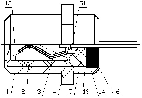
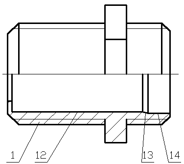
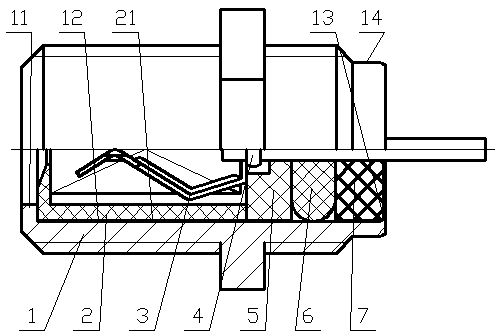
[0019] As shown in the figure, a coaxial radio frequency connector includes a housing 1, a central conductor is arranged inside the housing 1, and a front insulating part 2 and a rear insulating part 5 are respectively arranged on both sides of the central conductor. The insulators 5 are nested at both ends of the center conductor one by one, the front insulator 2 and the rear insulator 5 are embedded in the housing 1; the outer end of the rear insulator 5 is sealed by a sealant 6; the center conductor is formed by a contact spring 3 and PIN pin 4 are connected by riveting or welding. The rear side of the central conductor is fitted with a rear insulator 5, and the front side is fitted with a front insulator 2. The front insulator 2 and the rear insulator 5 are fitted with a central conductor and then embedded into the shell. 1, the rear insulator 5 and the inner hole of the housing 1 are installed through interference fit; there is a certain distance between the outer end surf...


PUM


Abstract

The present invention provides a coaxial radio frequency connector. A front insulation piece and a rear insulation piece are respectively arranged at two sides of a center conductor of the internal portion of a housing, the front insulation piece and the rear insulation piece are nested in two ends of the center conductor in tandem and then is embedded in the housing; and the outer end of the rearinsulation piece is sealed by employing a sealant. The coaxial radio frequency connector is good in electrical connection performance and little in signal attenuation, reduces the production and manufacturing cost and reduces the resource consumption.

Description

technical field [0001] The invention relates to a coaxial radio-frequency connector connected between a radio frequency head and a set-top box of a satellite antenna for receiving and transmitting signals, in particular to an F-type and FL10-type coaxial radio-frequency coaxial connector. Background technique [0002] Coaxial RF connectors between signal transmission and receiving components such as satellite antenna tuners and set-top boxes are generally composed of inner conductors, spring sheets, intermediate insulators, and outer conductors, which are sequentially plugged and assembled. The specific structure is as follows: Figure three As shown, the contact reed 3 and the PIN pin 4 are riveted or welded to form the inner conductor assembly, and the outer periphery of the PIN pin tail at the rear section of the inner conductor assembly is sequentially sleeved with the insulating middle piece 5, the sealing ring 6, and the insulating upper cover 7, extending into the shell...

Claims


Application Information

Patent Timeline
Patent Type & Authority Applications(China)
IPC IPC(8): H01R13/52H01R13/40H01R13/502H01R13/516H01R24/40
CPCH01R13/40H01R13/502H01R13/516H01R13/5202H01R24/40H01R2201/02
Inventor 沈学光晏明
Owner JIANGSU MINGLIAN ELECTRONICS TECH
Why Eureka
Try Eureka