
Ground gas extraction well drillingwell bore structure provided with flexible production casing pipe

A gas drainage and well structure technology, which is applied in casing, drilling equipment, wellbore/well components, etc., can solve the problems of affecting gas drainage effect, small deflection, weak shear deformation ability, etc.

Inactive Publication Date: 2018-03-16
CHINA UNIV OF MINING & TECH
View PDF4 Cites 0 Cited by
  • Summary
  • Abstract
  • Description
  • Claims
  • Application Information

AI Technical Summary

Problems solved by technology

However, under high-intensity mining conditions, the relative dislocation between rock formations will be greater, and the dislocation of rock formations and cementing casings will inevitably produce shearing effects on the internal production casings. Since the drilling production casings are all made of Rigid pipes such as oil casings and seamless steel pipes have small deflection in local areas, and their shear deformation ability is extremely weak under stress conditions, that is, shear fracture will occur when a small shear deformation occurs. Therefore, in Under high-strength mining conditions, the production casing often shears and breaks, which seriously affects the gas drainage effect and increases the cost of gas drainage
Although the method of increasing the diameter of the drilling wellbore and casing can reduce the impact of casing shear deformation or fracture on gas drainage, this method will greatly increase the construction cost of drilling, and increase the difficulty of drilling construction, affecting promoted its application

Method used


Image

  • Ground gas extraction well drillingwell bore structure provided with flexible production casing pipe
  • Ground gas extraction well drillingwell bore structure provided with flexible production casing pipe
  • Ground gas extraction well drillingwell bore structure provided with flexible production casing pipe

Examples


Embodiment Construction

[0015] An embodiment of the present invention will be further described below in conjunction with accompanying drawing:

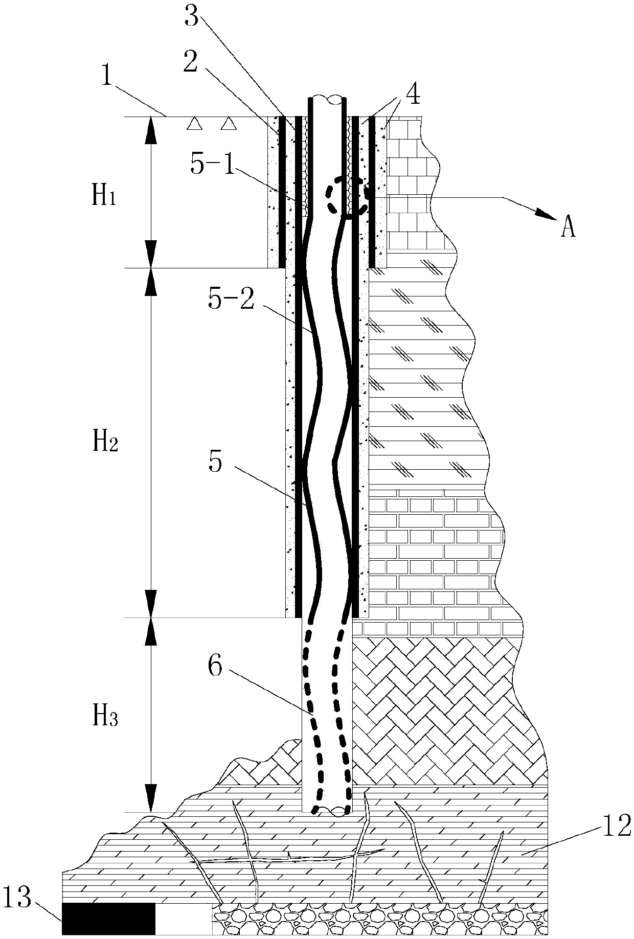
[0016] like figure 1 As shown, the present invention is equipped with a ground gas drainage drilling well structure with flexible production casings. The entire well drilling well is divided into three sections whose apertures are successively reduced from the surface 1 to the mining fracture zone 12: the surface hole section H1 , rock formation hole section H2 and pressure relief drainage hole section H3. A surface casing 2 reinforced with cement slurry 4 is arranged in the surface hole section H1, and a rock casing 3 reinforced with cement slurry 4 is arranged in the rock formation hole section H2 and the surface hole section H1; the surface casing 2 and the rock section casing 3 can be Prevent the well wall of the upper section from collapsing during drilling and affect the normal drilling; pressure relief and drainage section H3 open hole completion. ...


PUM


Abstract

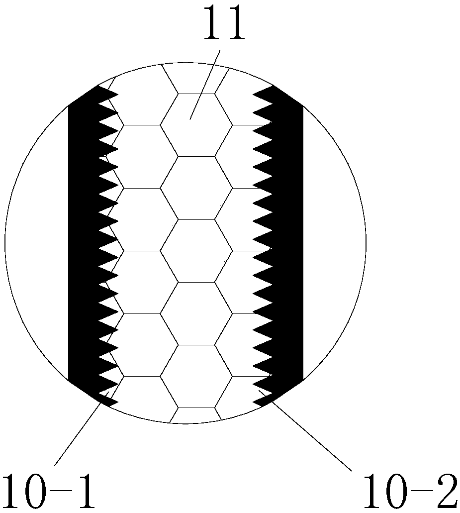
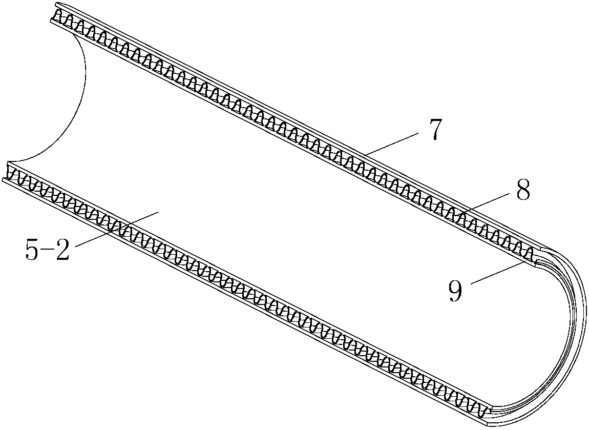
The invention discloses a ground gas extraction well drilling well bore structure provided with a flexible production casing pipe. The well bore structure is divided into three sections of a surface layer hole section, a rock stratum hole section and a pressure relief extraction hole section. The arranged production casing pipe penetrates through a whole well bore, the upper section, as long as 15-40 m, of the production casing pipe is a rigid casing pipe body, and the rest lower portion of the production casing pipe is a metallic flexible casing pipe body. The metallic flexible casing pipe body is divided into three layers, the outer layer is a metallic net sleeve, the middle layer is a metallic corrugated pipe, and the inner layer is a rubber hose. When adjacent rock stratums conduct relative movement, the metallic flexible casing pipe body can bend and deform along with the relative movement of the rock stratums, accordingly the shear acting force is unloaded, and the probability that the metallic flexible casing pipe body is sheared to fracture is lowered. The problem that the well drilling production casing pipe is sheared to fracture in the high strength extraction process ofa coal bed is solved, and extraction of well drilling for a long time is achieved. The well drilling well bore structure is convenient to construct, simple in structure and easy to promote.

Description

Technical field: [0001] The invention relates to a well body structure, in particular to a surface drilling well body structure suitable for gas extraction with a flexible pipe, and belongs to the technical field of gas drainage. technical background: [0002] Gas drainage is the fundamental measure to prevent and control gas disasters. Among all drainage methods, surface vertical drilling (referred to as "surface drilling") is an extremely efficient method of extracting dynamic pressure relief gas, which has a large drainage flow rate and high concentration, and has been obtained in many high-gas mining areas across the country. Promote apps. In the process of surface drilling, in order to avoid the impact of normal drilling due to well wall collapse, cementing casings must be installed section by section to protect the wellbore; The production casing is installed in the section or the whole wellbore. During drilling and drainage, the mining pressure relief gas enters th...

Claims


Application Information

Patent Timeline
IPC IPC(8): E21B17/00E21B17/20E21B43/00B32B15/02B32B15/04B32B15/06B32B25/04B32B1/08
CPCE21B17/00B32B1/08B32B5/028B32B15/02B32B15/043B32B15/06B32B2597/00E21B17/20E21B43/006
Inventor 刘应科周福宝谭东升田辉
Owner CHINA UNIV OF MINING & TECH
Learn More