
Punching machine capable of changing punching direction for hub

A technology of punching machine and wheel hub, applied in the field of punching machine, can solve the problems of easy generation of temperature on the surface of the wheel hub, increase the labor force of employees, and difficult to take the wheel hub, so as to solve the inaccurate lateral positioning, improve the heat dissipation effect, and improve the cooling effect. Effect

Inactive Publication Date: 2018-03-20
蒋嘉文
View PDF0 Cites 0 Cited by
  • Summary
  • Abstract
  • Description
  • Claims
  • Application Information

AI Technical Summary

Problems solved by technology

[0003] The purpose of the present invention is to provide a punching machine with a changeable punching direction for the wheel hub, which has the advantages of freely changing the processing punching direction and air-cooled cooling, and solves the problem that the existing punching machine can only punch in one direction. Drilling, when it is necessary to drill holes in different directions of the coupling, it is necessary to change the direction continuously, which not only wastes time but also increases the labor force of the employees, and after the hub is drilled, the surface of the hub is prone to temperature, and it is not easy to handle the processed hub. Take, the problem of low work efficiency

Method used


Image

  • Punching machine capable of changing punching direction for hub
  • Punching machine capable of changing punching direction for hub
  • Punching machine capable of changing punching direction for hub

Examples


Embodiment Construction

[0022] The following will clearly and completely describe the technical solutions in the embodiments of the present invention with reference to the accompanying drawings in the embodiments of the present invention. Obviously, the described embodiments are only some, not all, embodiments of the present invention. Based on the embodiments of the present invention, all other embodiments obtained by persons of ordinary skill in the art without making creative efforts belong to the protection scope of the present invention.

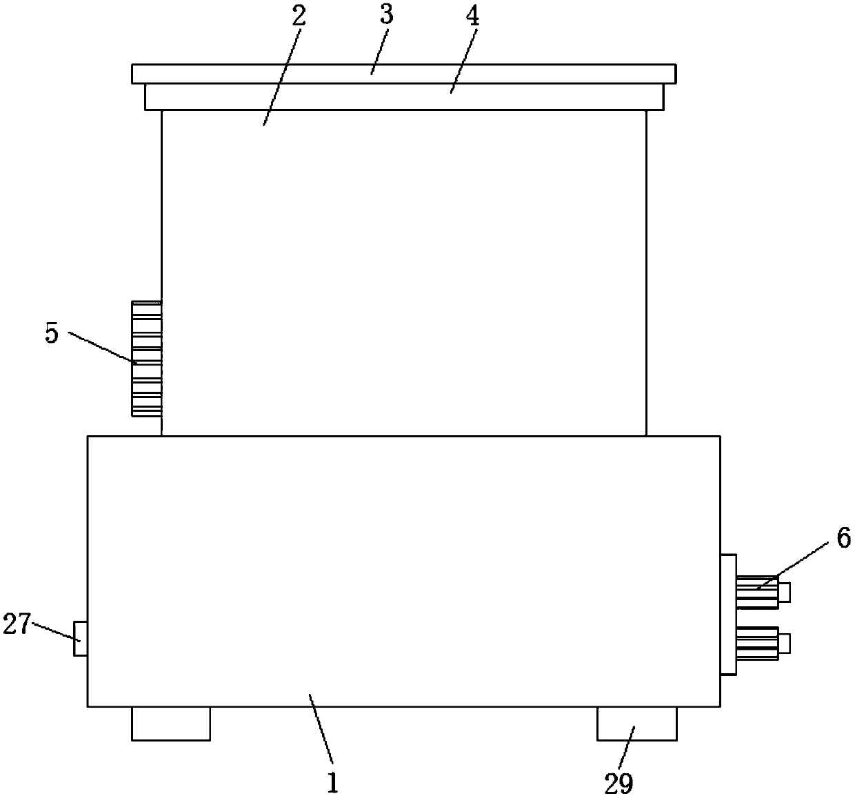
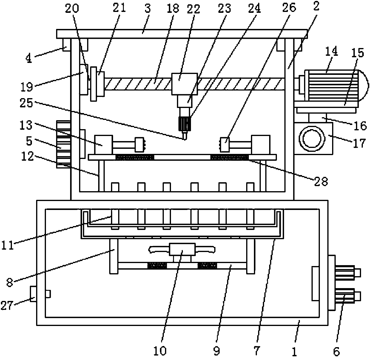
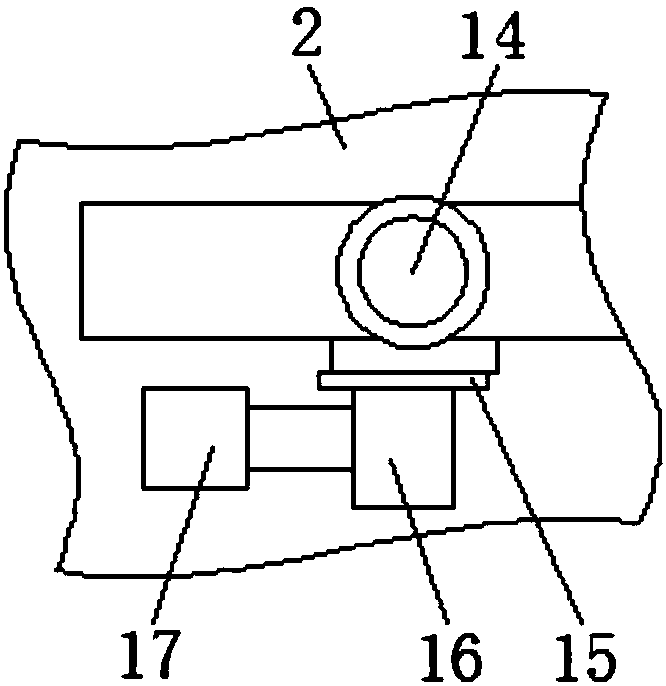
[0023] see Figure 1-3 , a punching machine for a wheel hub with a changeable punching direction, comprising a bellows (1), an organic body (2) is arranged on the top of the bellows (1), and a movable plug (27) is arranged on the outside of the bellows (1), and One end of the movable plug (27) runs through the bellows (1) and extends to the inside of the bellows (1). The movable plug (27) can effectively increase the flow of wind speed inside the bellows (1), ...


PUM

PropertyMeasurementUnit
heightaaaaaaaaaa

Abstract

The invention discloses a punching machine with a changeable punching direction for a wheel hub, which comprises a bellows, an organic body is arranged on the top of the bellows, an organic cover is arranged on the top of the machine body, an annular slot is arranged on the bottom of the machine cover, and the top of the The inside of the annular card slot and the outside of the body are provided with a cooling fan. The air outlet end of the cooling fan runs through the body and extends to the inside of the body. A high-pressure fan is arranged outside the bellows. The outlet end of the high-pressure fan runs through the bellows and extends to the bellows The inner wall of the internal bellows is fixedly connected with an air collecting plate, and the bottom of the air collecting plate is fixedly connected with a symmetrical baffle, and the bottom of the air collecting plate is provided with an air outlet, and a mesh plate is arranged between the two baffles, and the mesh plate The two ends of the two baffles are respectively fixedly connected to the opposite sides of the two baffles. The invention enables the whole to change direction flexibly, and can rapidly cool the processed wheel hub, save working time, reduce labor intensity of employees, and improve work efficiency.

Description

technical field [0001] The invention relates to the technical field of mechanical processing, in particular to a punching machine for a wheel hub which can change the punching direction. Background technique [0002] Machining refers to the process of changing the shape or performance of a workpiece through a mechanical device. According to the difference in processing methods, it can be divided into cutting processing and pressure processing. With the development of modern machinery industry, in the field of automobile processing, The processing of automobile wheels often uses a punching machine. The punching machine is completed by the cooperation of four parts. First, the material is moved to the scanning area of ​​the camera of the automatic punching machine. After the image is scanned by the camera, it is processed and given to the control part. Signal, after the control part receives the signal, it further processes and controls the action of the transmission part, so ...

Claims


Application Information

Patent Timeline
Patent Type & Authority Applications(China)
IPC IPC(8): B23B39/00B23Q3/06B23Q11/12
CPCB23B39/006B23Q3/06B23Q11/126
Inventor 蒋嘉文
Owner 蒋嘉文
Learn More