Conveying equipment for automated production line for steel grid plates

An automated production line and conveying equipment technology, applied in the field of steel grating manufacturing, can solve the problems of complex equipment, low degree of production automation, and low production efficiency, and achieve the effects of simplifying the operation process steps, ensuring product consistency, and improving the degree of automation

Pending Publication Date: 2018-03-20
张文安
View PDF8 Cites 4 Cited by
  • Summary
  • Abstract
  • Description
  • Claims
  • Application Information

AI Technical Summary

Problems solved by technology

[0002] Steel grating, also known as grid plate, is a kind of steel product that is cross-arranged with flat steel according to a certain spacing and cross bars, and welded into a square grid in the middle. Steel grating is mainly used as a gutter cover, steel structure Platform boards, steel ladder pedal boards, etc. Steel gratings have ventilation, lighting, heat dissipation, anti-skid, explosion-proof and other properties. At present, the production of steel gratings is mainly produced by large-scale professional welding equipment. Steel top, and then implement pressure welding on the cross bar to weld the cross bar and flat steel into shape. This welding equipment has complicated equipment and a large impact on the power grid, and the initial equipment investment is huge; in the prior art, the welding of flat steel and cross bar Most of them still use the manual welding method, the quality of the welding points is poor, the efficiency is low, it is easy to cause missing welding and false welding, and the consistency of the welding points is poor, resulting in a low pass rate of the finished steel grating. For example: the publication number is : The patent document of "CN102853245A" discloses a kind of steel grating and used equipment and production method, steel grating comprises flat steel and cross bar, and each flat steel is provided with through hole, and cross bar passes through the corresponding passage of flat steel There is an indentation groove on the top of the flat steel; the indentation groove corresponds to the lower cross bar to form an extrusion pit, and the left and right bulges are formed on both sides of the extrusion pit, and the outer wall of the through hole of the flat steel is clamped on the Between the above-mentioned left bulge and the right bulge; or the indentation groove corresponds to the lower cross bar with a card slot, and the outer wall of the through hole is snapped into the card slot
The equipment for producing steel gratings of the present invention includes a pressure head and the first slot template. The invention also provides a method for producing steel gratings, which includes the following steps: processing flat steel through holes; 1. In the flat steel groove of the slot template; pass the cross bar through the corresponding through hole of the flat steel, and the baffle will position the cross bar; use a press with a pressure head to press the top of the flat steel through hole; use this In the technical solution of the invention, since a through hole is set at the corresponding position on the flat steel, the cross bar penetrates through the through hole, so that the finished steel grating has better structural strength, but the welding method still uses the manual welding method, and the welding The point consistency is not easy to guarantee, and it is easy to cause virtual welding, missing welding and other phenomena. In addition, because there is no good pre-positioning between the cross bar and the flat steel, during the welding process, the high temperature generated by welding will cause the cross bar or flat steel to be easily damaged. Deformation affects the manufacturing accuracy of the finished steel grating, the degree of production automation is low, and it takes more man-hours to process through holes on the flat steel, the positioning is not accurate, and the production efficiency is not high

Method used


Image

  • Conveying equipment for automated production line for steel grid plates
  • Conveying equipment for automated production line for steel grid plates
  • Conveying equipment for automated production line for steel grid plates

Examples


Embodiment Construction

[0029] The technical solution of the present invention is further described below, but the scope of protection is not limited to the description.

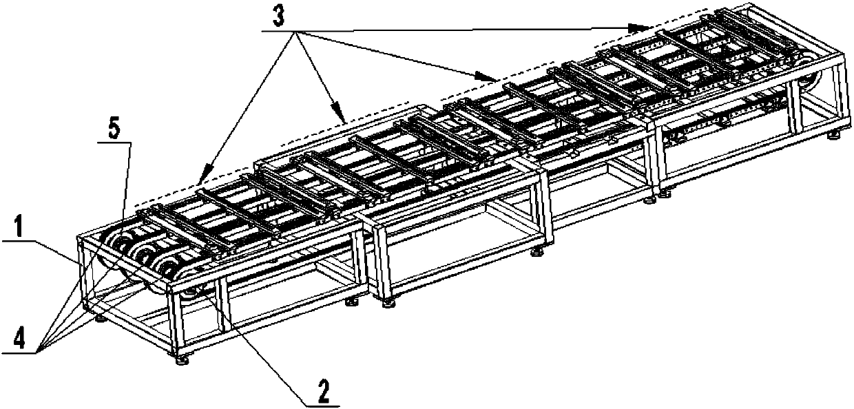
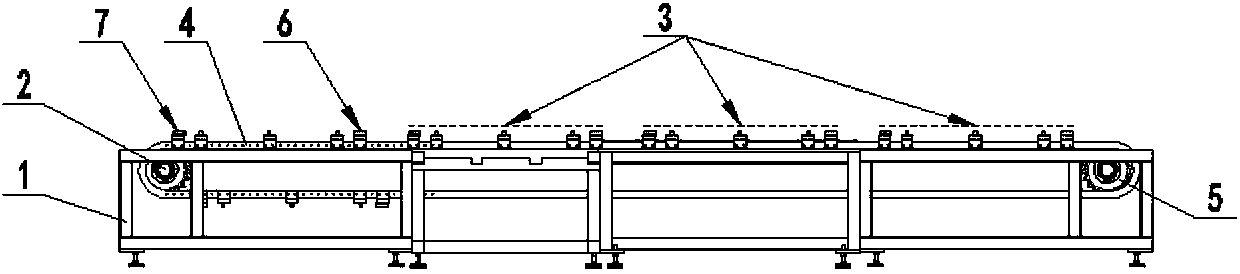
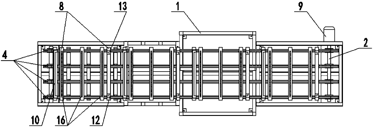
[0030] The invention provides a conveying equipment for steel grating automatic production line, such as Figure 1 to Figure 11 As shown, it includes a frame 1, a drive shaft 2, multiple sets of clamp mechanisms 3 and a plurality of drive belts 4, and the two ends of the drive shaft 2 are installed on both sides of the frame 1 through bearing seats respectively, and each drive shaft 2 is provided with There are a plurality of transmission wheels 5 with the same number, and each transmission belt 4 is meshed with the transmission wheels 5 at the corresponding positions of all transmission shafts 2, and each set of clamp mechanism 3 includes a limiting device A6, a limiting device B7 and at least two clamps The support plate 8, each clamp support plate 8 is installed on the transmission belt 4, and the limit device A6 and the limit d...


PUM


Abstract

The invention provides conveying equipment for an automated production line for steel grid plates. The conveying equipment comprises a rack, transmission shafts, multiple clamp mechanisms and multipletransmission belts. The two ends of the transmission shafts are mounted at the two sides of the rack through bearing seats correspondingly. Each transmission shaft is provided with multiple transmission wheels, wherein the number of the transmission wheels on one transmission shaft is the same as that of the transmission wheels on another transmission shaft. Each transmission belt is connected with the transmission wheels at the corresponding positions of all the transmission shafts an engaged manner. Each clamp mechanism comprises a limiting device A, a limiting device B and two or more clamp bearing plates. Each clamp bearing plate is mounted on the corresponding transmission belt. Each limiting device A and the corresponding limiting device B are mounted on the corresponding clamp bearing plates correspondingly. By means of the conveying equipment, all the clamp mechanisms used in all procedures for producing the steel grid plates are unified into the fixed form and mounted on an annular conveying belt of a conveying mechanism, so that the clamp mechanisms enable the manufacturing procedure positions to be changed with operation of the conveying belt; the automation level of steel grid plate production is raised; and product precision, quality and conformance are improved.

Description

technical field [0001] The invention relates to the technical field of steel grating manufacturing, in particular to a conveying device for an automatic steel grating production line. Background technique [0002] Steel grating, also known as grid plate, is a kind of steel product that is cross-arranged with flat steel according to a certain spacing and cross bars, and welded into a square grid in the middle. Steel grating is mainly used as a gutter cover, steel structure Platform boards, steel ladder pedal boards, etc. Steel gratings have ventilation, lighting, heat dissipation, anti-skid, explosion-proof and other properties. At present, the production of steel gratings is mainly produced by large-scale professional welding equipment. Steel top, and then implement pressure welding on the cross bar to weld the cross bar and flat steel into shape. This welding equipment has complicated equipment and a large impact on the power grid, and the initial equipment investment is hu...

Claims


Application Information

Patent Timeline
Patent Type & Authority Applications(China)
IPC IPC(8): B65G15/58
CPCB65G15/58
Inventor 张文安
Owner 张文安
Why Eureka
Try Eureka