
Top polarity testing and output value fault detection method

A fault detection and polarity test technology, applied in the detection field, can solve problems affecting the correctness of fault detection algorithm design and diagnosis, complex detection algorithms, and safe operation risks, so as to improve test safety, simplify the test process, reduce The effect of small errors

Active Publication Date: 2018-03-20
SHANGHAI SATELLITE ENG INST
View PDF7 Cites 8 Cited by
  • Summary
  • Abstract
  • Description
  • Claims
  • Application Information

AI Technical Summary

Problems solved by technology

[0003] When testing the polarity and output value of a stand-alone gyro, the gyro is usually placed on a two-dimensional turntable, and the turntable rotates at a specified angular velocity to record the gyro output and judge the polarity of the gyro. The gyro is installed behind the satellite, and the satellite is relatively large in size and weight. If Using the conventional two-dimensional turntable rotation for testing, the workload is relatively large, and there is a risk of safe operation, especially for large satellites, the gyro installation configurations include the main and standby 3 orthogonal configurations, 3 orthogonal + 1 oblique configuration, The configuration often affects the design of the fault detection algorithm and the correctness of diagnosis. Many studies have been carried out on the fault detection of gyroscopes at home and abroad, mainly using probability statistics, attitude kinematics, etc., focusing on orthogonal installation configuration, the inclined-mounted gyroscope mainly uses the balance equation method for fault detection, and the detection algorithm is relatively complicated

Method used


Image

  • Top polarity testing and output value fault detection method
  • Top polarity testing and output value fault detection method
  • Top polarity testing and output value fault detection method

Examples


Embodiment Construction

[0032] The preferred embodiments of the present invention are given below in conjunction with the accompanying drawings to describe the technical solution of the present invention in detail.

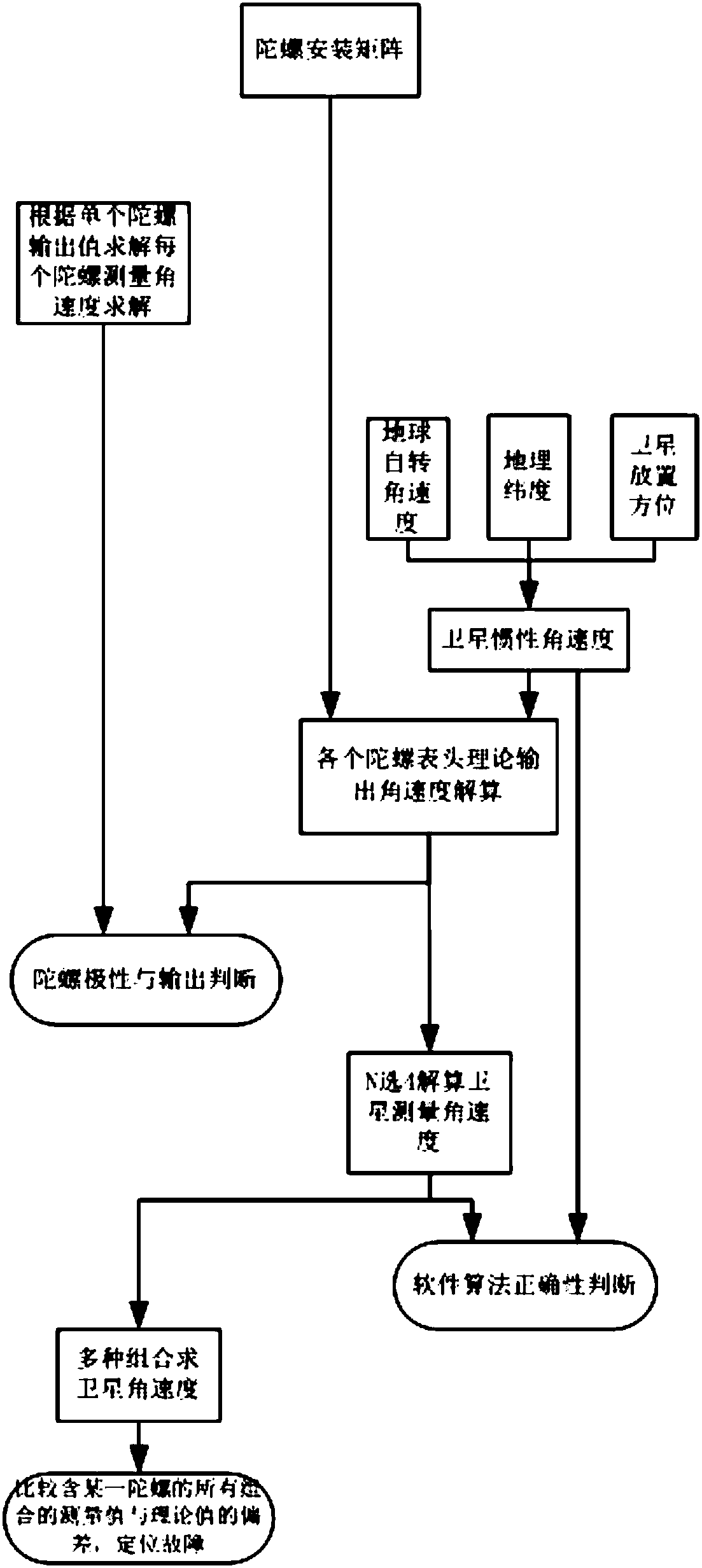
[0033] Such as figure 1 As shown, the gyroscope polarity test and the output value fault detection method of the present invention comprise the following steps:

[0034] Step 1, gyro installation matrix description;

[0035] Step 2, solving the angular velocity measured by the gyroscope;

[0036] Step 3, using the earth's rotation angular velocity to solve the theoretical value of satellite inertial angular velocity and gyro output;

[0037] Step 4, satellite inertial measurement angular velocity solution;

[0038] Step 5: Locate the faulty gyro by combining various gyro heads.

[0039] In said step 1, according to the actual installation direction of the gyroscope head, a 3×N matrix A is used to describe the gyroscope installation matrix, and N is the number of gyroscope heads on th...


PUM


Abstract

The invention discloses a top polarity testing and output value fault detection method. The method comprises the following steps: firstly, describing a top mounting matrix; secondly, solving top measurement angular velocity; thirdly, resolving satellite inertial angle speed and top output theoretical value by utilizing rotational angular velocity of the earth; fourthly, solving satellite inertialmeasurement angular velocity; and fifthly, locating a top in a fault state by utilizing multiple combinations of top headers. The method disclosed by the invention has the advantages that top polarityand output value can be conveniently and accurately tested, mutual fault monitoring among tops can be realized, a top whole satellite state testing process can be simplified, requirement on test equipment is lowered, workload is reduced, and the method disclosed by the invention not only can be applied to a top whole satellite testing process but also can be applied to a one machine level and system level testing process.

Description

technical field [0001] The invention relates to a detection technology, in particular to a gyroscope polarity test and output value fault detection method. Background technique [0002] The gyroscope is an indispensable inertial measurement sensor in the field of satellite control. The output measurement value of the gyroscope is related to the safety and success of the satellite on-orbit control. Once the positive and negative polarity is wrong, the satellite attitude and orbit control computer will output the opposite control. Torque may cause fatal damage to satellites. Most satellites in orbit operate at low angular velocities. Therefore, the polarity test under low angular velocity conditions is more important. The accuracy of gyro output directly determines the attitude control of satellites. Therefore, it is necessary to quickly and easily detect the correctness of the output value of the gyroscope, especially now that satellites have higher and higher requirements fo...

Claims


Application Information

Patent Timeline
IPC IPC(8): G01C25/00
CPCG01C25/005
Inventor 边志强栗双岭曾擎朱海江向明江王田野洪振强许海玉崔华
Owner SHANGHAI SATELLITE ENG INST
Learn More