
Use the voltage detection circuit on io

A voltage detection circuit, power supply voltage technology, applied in the direction of measuring current/voltage, measuring device, measuring electrical variables, etc., can solve problems such as increasing cost, and achieve the effect of optimizing performance

Active Publication Date: 2020-06-05
SHANGHAI HUAHONG GRACE SEMICON MFG CORP
View PDF4 Cites 0 Cited by
  • Summary
  • Abstract
  • Description
  • Claims
  • Application Information

AI Technical Summary

Problems solved by technology

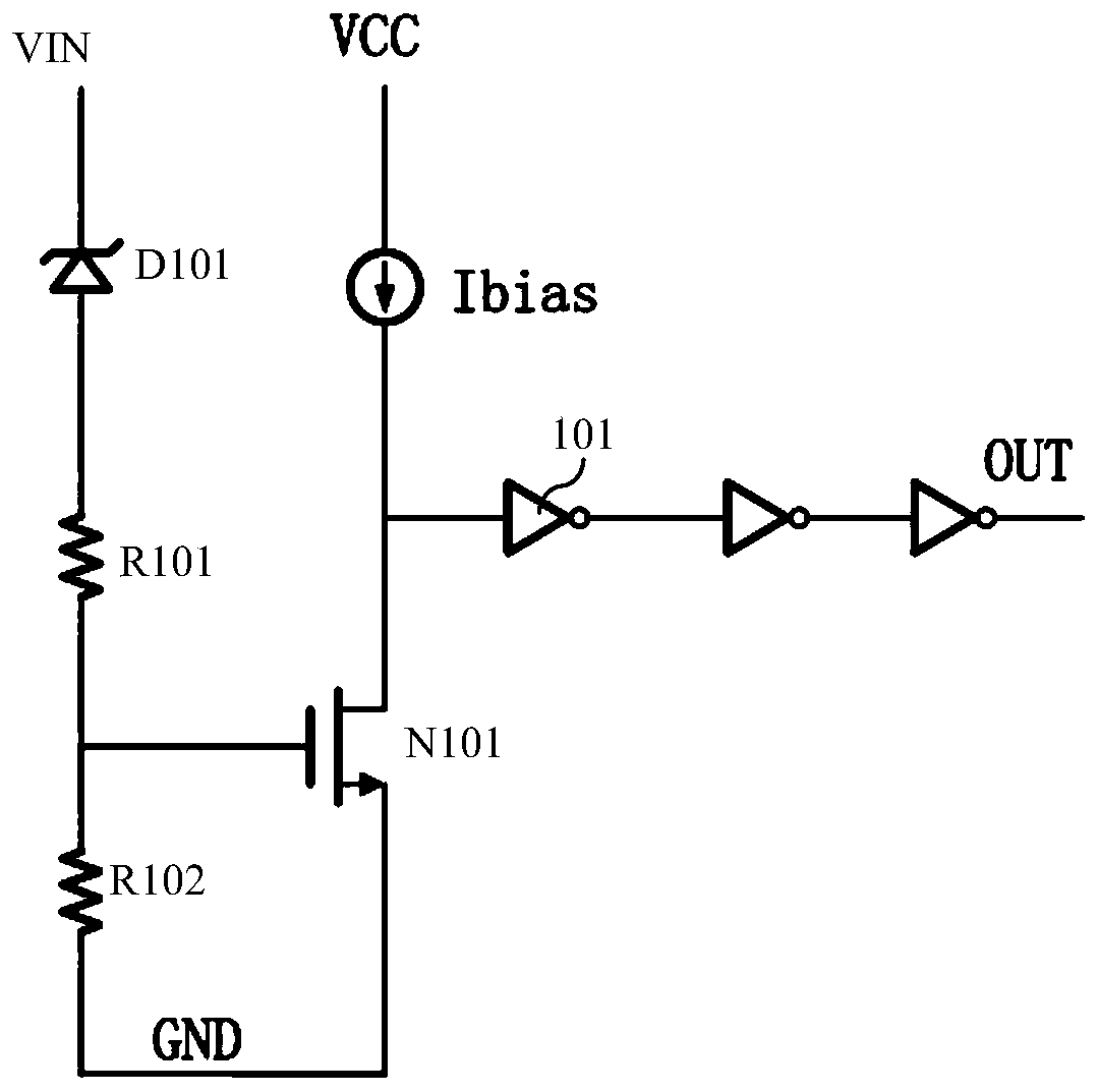
[0003] Existing circuits for detecting high-voltage signals in IO generally use zener tubes, but in standard CMOS processes, adding a zener tube requires an additional mask, which increases the cost

Method used


Image

  • Use the voltage detection circuit on io
  • Use the voltage detection circuit on io

Examples


Embodiment Construction

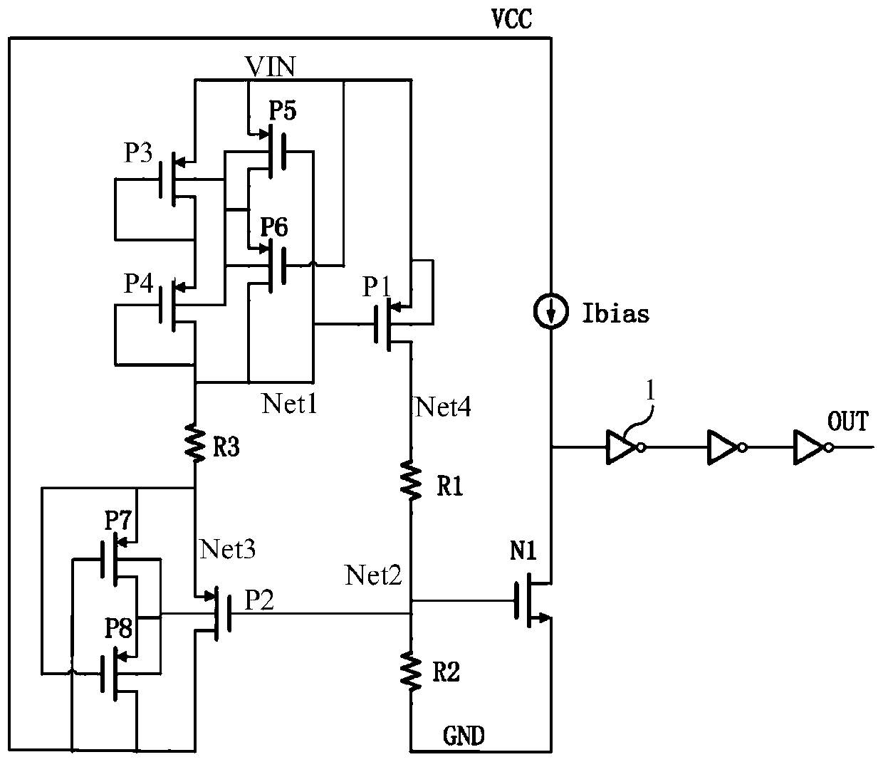
[0041] Such as figure 2 Shown is a circuit diagram of the voltage detection circuit used on the IO in the embodiment of the present invention. The voltage detection circuit used in the IO in the embodiment of the present invention includes:

[0042] The input signal VIN is connected to the input terminal of the voltage detection circuit. The input signal VIN includes three states of 0V, power supply voltage VCC and high voltage VHV, and the high voltage is greater than the power supply voltage VCC.

[0043] The voltage detection circuit includes:

[0044] A series structure of a plurality of PMOS transistors connected in series in a diode connection manner, the series structure of PMOS transistors is connected between the input signal VIN and the first node Net1.

[0045] The first PMOS transistor P1, the source of the first PMOS transistor P1 is connected to the input signal VIN, and the gate of the first PMOS transistor P1 is connected to the first node Net1.

[0046] The...


PUM


Abstract

The invention discloses a voltage detection circuit on IO. The voltage detection circuit on IO includes a PMOS transistor serial structure which is formed through serial connection of a plurality of PMOS transistors in a diode connection mode, wherein the PMOS transistor serial structure is connected between an input signal and a first node; the source electrode of the first PMOS transistor is connected with the input signal, and the grid electrode of the first PMOS transistor is connected with the first node; a first resistor and a second resistor are connected in series between the drain electrode of the first PMOS transistor and the ground, and the connection point between the first resistor and the second resistor is the second node which outputs a detection signal; a third resistor isconnected between the first node and the source electrode of the second PMOS transistor, and the drain electrode of the second PMOS transistor is connected with the power supply voltage, and the gridelectrode of the second PMOS transistor is connected with the second node, and the source electrode of the second PMOS transistor is a third node; and each PMOS transistor utilizes the transistor technological structure taking the working voltage as the power supply voltage. The voltage detection circuit on IO is implemented by using the transistor technological structure of the power supply voltage, and does not need Zeners so as to save one layer of photomask to save the cost.

Description

technical field [0001] The invention relates to a semiconductor integrated circuit, in particular to a voltage detection circuit used on an IO. Background technique [0002] In some applications, in order to save the PIN pin of the chip, there will be an additional high-voltage input state in the conventional digital input and output ports (IO), which requires the IO to be able to detect and identify. In this application, the general power supply voltage VCC ranges from 1.8V to 5.5V, and the input signal is in three states of 0, VCC and VHV. VHV means a high voltage greater than VCC, so a module is required in the IO to detect whether the input signal is high voltage. Signal. [0003] Existing circuits for detecting high-voltage signals in IO generally use Zener tubes, but in a standard CMOS process, adding a Zener tube requires adding a mask, which increases the cost. [0004] Such as figure 1 Shown is the circuit diagram of the existing voltage detection circuit used on...

Claims


Application Information

Patent Timeline
Patent Type & Authority Patents(China)
IPC IPC(8): G01R19/165
CPCG01R19/16519G01R19/16557G01R19/16576
Inventor 唐成伟
Owner SHANGHAI HUAHONG GRACE SEMICON MFG CORP
Learn More