Piezoelectric energy collector

A piezoelectric energy and harvester technology, applied in electrical components, piezoelectric effect/electrostrictive or magnetostrictive motors, generators/motors, etc. And other issues

Active Publication Date: 2018-03-20
SYSU CMU SHUNDE INT JOINT RES INST +1
View PDF4 Cites 4 Cited by
  • Summary
  • Abstract
  • Description
  • Claims
  • Application Information

AI Technical Summary

Problems solved by technology

However, the cantilever beam material selected by this device has relatively poor flexibility and bending degree, and only when the frequency of the vibration source is equal to the resonant frequency of the device, the voltage output is relatively high, so there is a single resonant frequency, narrow bandwidth, and low power generation. Defects, unable to meet the needs of collection and storage
In addition, the device is less sensitive to vibration, that is, the vibration starting condition is relatively high, and the mass of the entire power generation device (including the mass block) is heavy, which reduces the tendency of free swinging up and down

Method used

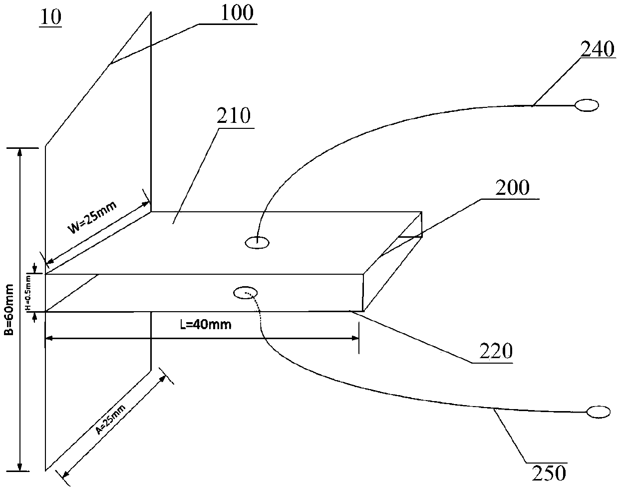
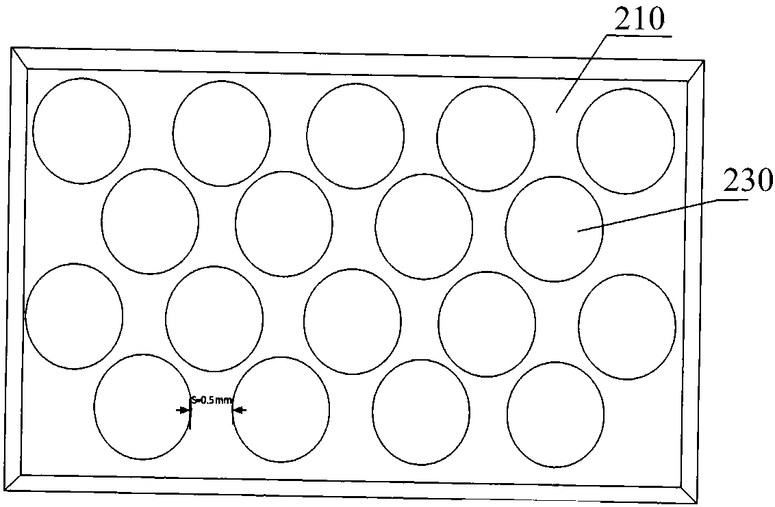
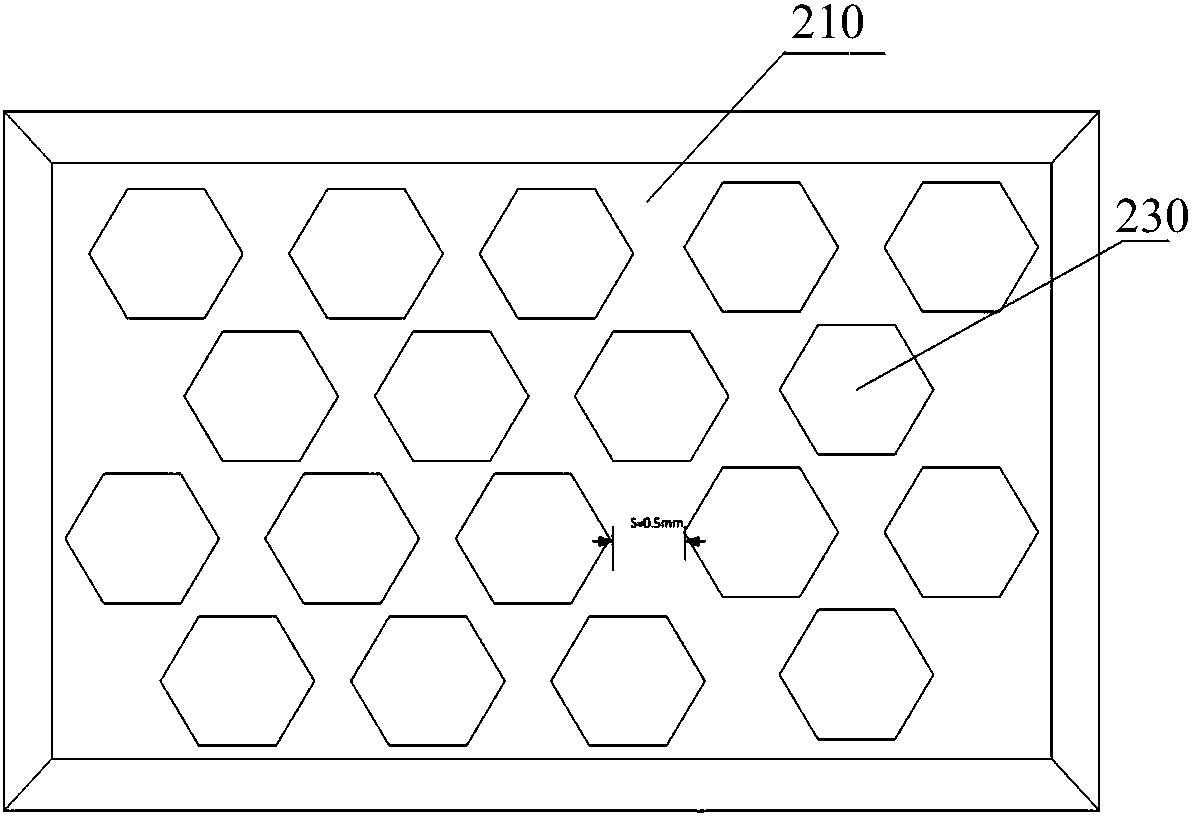

Image

  • Piezoelectric energy collector
  • Piezoelectric energy collector
  • Piezoelectric energy collector

Examples


Embodiment Construction

[0021] In order to facilitate the understanding of the present invention, the present invention will be described more fully below with reference to the associated drawings. Preferred embodiments of the invention are shown in the accompanying drawings. However, the present invention can be embodied in many different forms and is not limited to the embodiments described herein. On the contrary, these embodiments are provided to make the understanding of the disclosure of the present invention more thorough and comprehensive.

[0022] It should be noted that when an element is referred to as being “fixed” to another element, it can be directly on the other element or there can also be an intervening element. When an element is referred to as being "connected to" another element, it can be directly connected to the other element or intervening elements may also be present.

[0023] Unless otherwise defined, all technical and scientific terms used herein have the same meaning as...


PUM

PropertyMeasurementUnit
Diameteraaaaaaaaaa
Diagonal lengthaaaaaaaaaa
Thicknessaaaaaaaaaa

Abstract

The invention relates to a piezoelectric energy collector, which is characterized in that two flexible circuit boards are adopted to clamp piezoelectric ceramic pieces so as to form a piezoelectric unit. The piezoelectric energy collector adopts the flexible circuit board to serve as a substrate of the piezoelectric unit, thereby being high in flexibility, having good conductivity and being convenient for installation and welding. The flexible circuit board can be freely bent, wound and folded, can also stretch and move at will and has the characteristics of light weight and thin thickness, thereby being capable of greatly reducing the size and the weight of the whole piezoelectric energy collector. The flexible circuit board is flexible and high in sensitivity for vibration and can perceive the shake as long as the shake exists, thereby significantly improving the sensitivity of the piezoelectric energy collector for vibration. The piezoelectric unit is provided with a plurality of piezoelectric ceramic pieces and forms a honeycomb structure, so that the piezoelectric energy collector has a plurality of resonant frequency points, can sense the vibration energy of different frequencies in the environment, is wide in bandwidth and facilitates to improving the output voltage of the whole piezoelectric energy collector.

Description

technical field [0001] The invention relates to the field of energy equipment, in particular to a piezoelectric energy harvester. Background technique [0002] The energy issue is the most concerned hot topic in the world today. Researchers from various countries have been working hard to find and develop new energy sources. In recent years, with the rapid development of wireless sensor networks, wireless sensor networks have been widely used. In particular, the size reduction, light weight and power consumption of sensing nodes are greatly reduced, so sensing nodes are widely used in various fields, such as in industry, agriculture, communication, national defense, aerospace, and medical fields. Sensor nodes with low power consumption, small size and low cost can form a distributed and self-organizing wireless sensor network through wireless communication. Most wireless sensor networks are powered by batteries, but wireless sensors are small in size and have limited batt...

Claims


Application Information

Patent Timeline
IPC IPC(8): H02N2/18
CPCH02N2/188
Inventor 高荣岗郭远祥叶涛
Owner SYSU CMU SHUNDE INT JOINT RES INST
Why Eureka
Try Eureka