Construction method for building board cutting device

A technology for building boards and cutting devices, which is applied in the direction of shearing devices, manufacturing tools, metal processing equipment, etc., can solve the problems of poor quality of manual cutting, scattering, and large waste of materials, etc., to suppress dust scattering, increase cutting speed, The effect of ensuring breathing safety

Inactive Publication Date: 2018-03-23
罗艳春
View PDF0 Cites 4 Cited by
  • Summary
  • Abstract
  • Description
  • Claims
  • Application Information

AI Technical Summary

Problems solved by technology

[0002] In the process of cutting floor and wall tiles for building decoration, it is inevitable to need to cut when laying floor and wall tiles. The common way of cutting and cutting floor and wall tiles is manual cutting. Manual cutting is flexible and convenient, but the quality of manual cutting is poor. , large dimensional error, large material waste, heavy follow-up processing workload, poor working conditions and low production efficiency
When cutting the floor manually, unskilled decoration workers often cannot cut the floor neatly into two halves, and sometim

Method used


Image

  • Construction method for building board cutting device
  • Construction method for building board cutting device

Examples


Embodiment

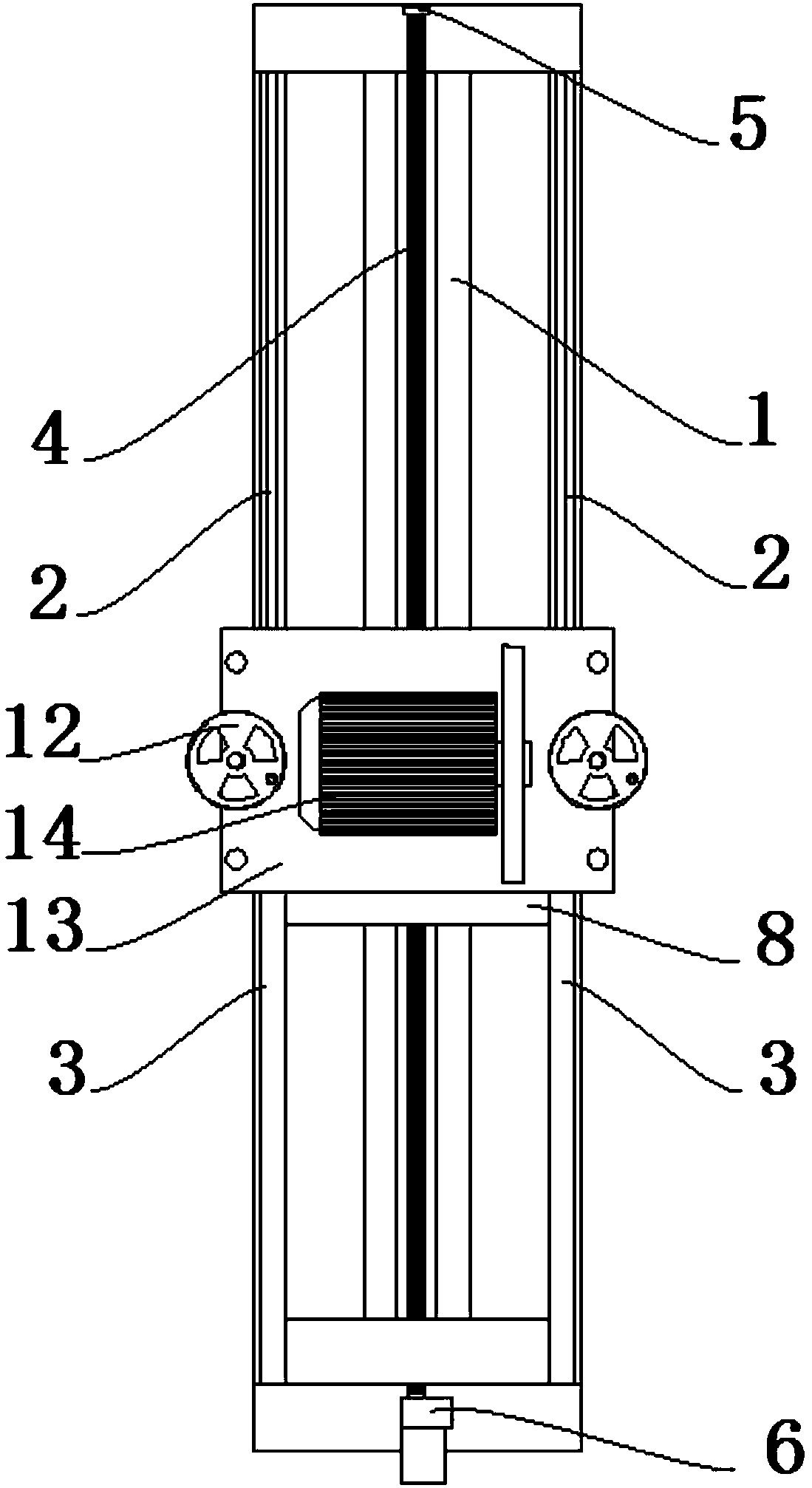
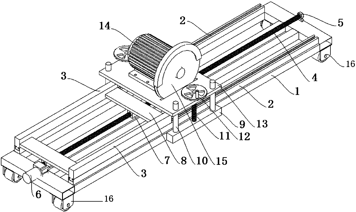
[0030] Such as figure 1 with figure 2 As shown, the present invention is used for the construction method of building plate cutting device, comprises the following steps:

[0031] Step 1. Transport the device to the setting station on the construction site, open the brake device on the casters 16, and fix the device at the setting station;

[0032] Step 2. Move the slider 3 on the guide rail 2, and move the slider 3 to the end of the device;

[0033] Step 3. Take a building board, place the building board flat on the top of the slider 3, mark the cutting line on the building board, and position the building board on the slider 3. The cutting line on the building board is located directly below the cutting piece 15 , fix the building board on the slider 3;

[0034] Step 4, measure the thickness of the building board, manually rotate the handwheel 12, adjust the height of the motor mounting plate 13 by rotating the hand wheel 12 according to the thickness of the building boa...

Embodiment approach

[0043]In a preferred embodiment, the device includes a base 1 and a cutting device. Guide rails 2 are fixedly installed on the left and right sides of the base 1. The two guide rails 2 are located at the same height on the base 1. The guide rails 2 are parallel to each other. The upper ends of the guide rails 2 are respectively A slide block 3 is matched, and screw rods 4 are arranged between the guide rails 2, and the screw rods 4 are parallel to the guide rails 2 respectively. One end of the screw rod 4 is fixedly connected to the base 1 through the screw bearing seat 5 , and the other end of the screw rod 4 is connected to the DC motor 6 through a shaft coupling, and the DC motor 6 is fixed on the base 1 . A screw nut 7 is matched with the screw mandrel 4, and a slider drive plate 8 is fixedly connected to the screw nut 7, and both ends of the slider drive plate 8 are respectively fixedly connected with the slider 3 on the guide rail 2. The top of base 1 is provided with cu...


PUM


Abstract

The invention discloses a construction method for a building plate cutting device, which comprises the following steps: the first step is to fix the device at the setting station; the second step is to move the slider to the end of the device; the third step is to take a For building boards, fix the building boards on the slider; the fourth step is to measure the thickness of the building boards, and manually rotate the handwheel until the outer circle of the cutting piece on the motor mounting plate intersects with the bottom surface of the building boards; fifth The first step is to power on the device; the sixth step is to press the motor start button on the electrical control box; the seventh step is to press the DC motor forward start button on the electrical control box; Spray water at the cutting position; the ninth step, after the building board is cut, press the motor stop button and the DC motor stop button on the electrical control box; the tenth step, the device is powered off; the eleventh step, take out the cut building board . The incision after cutting the building plate of the invention is smooth, and the construction speed is accelerated.

Description

technical field [0001] The invention relates to the technical field of building tools, in particular to a construction method for a building plate cutting device. Background technique [0002] In the process of cutting floor and wall tiles for building decoration, it is inevitable to need to cut when laying floor and wall tiles. The common way of cutting and cutting floor and wall tiles is manual cutting. Manual cutting is flexible and convenient, but the quality of manual cutting is poor. , large dimensional error, large material waste, heavy follow-up processing workload, poor working conditions and low production efficiency. When cutting the floor manually, unskilled decoration workers often cannot cut the floor neatly into two halves, and sometimes even break the whole floor, resulting in the scrapping of the whole floor. In the process of manual cutting The cut ash layer will be scattered throughout the construction site, which will bring great harm to the respiratory ...

Claims


Application Information

Patent Timeline
IPC IPC(8): B23D19/00B23Q11/10
CPCB23D19/00B23Q11/10
Inventor 罗艳春
Owner 罗艳春
Why Eureka
Try Eureka