
A method for detecting the contamination of the contact surface between mask plate and mask table

A reticle and reticle technology, which is applied in the photo-engraving process of the pattern surface, the original for photomechanical processing, the photo-engraving process exposure device, etc., can solve the problem of uneven placement, out-of-focus, partial Abnormal regional patterns and other problems, to achieve accurate detection results, reduce misjudgments and missed judgments

Active Publication Date: 2020-05-01
SHANGHAI HUAHONG GRACE SEMICON MFG CORP
View PDF5 Cites 0 Cited by
  • Summary
  • Abstract
  • Description
  • Claims
  • Application Information

AI Technical Summary

Problems solved by technology

However, during the storage of the mask plate and the transfer process of the robot arm, some pollutants may come into contact with it, which may cause the mask table to be contaminated during the contact process with the mask plate. If the contact surface between the mask plate and the mask table is polluted , will affect the alignment accuracy of the mask and cause alignment errors; and the contamination of the contact surface between the mask and the mask table will cause the mask to be placed unevenly and out of focus, resulting in abnormal patterns in local areas. Real-time monitoring of the contamination of the contact surface between the stencil and the mask table

Method used

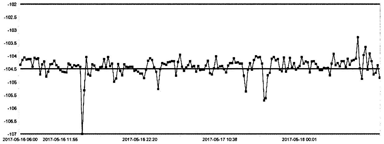
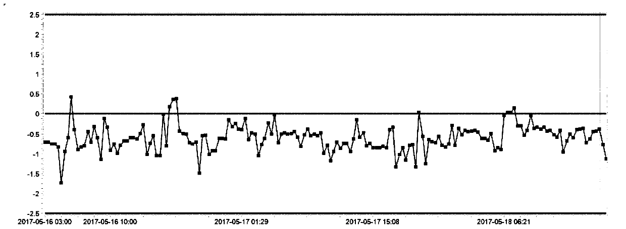

Image

  • A method for detecting the contamination of the contact surface between mask plate and mask table
  • A method for detecting the contamination of the contact surface between mask plate and mask table
  • A method for detecting the contamination of the contact surface between mask plate and mask table

Examples


Embodiment Construction

[0023] The method for detecting the contamination of the contact surface between the mask plate and the mask table proposed by the present invention will be further described in detail below with reference to the accompanying drawings and specific embodiments. Advantages and features of the present invention will be apparent from the following description and claims. It should be noted that all the drawings are in a very simplified form and use imprecise scales, and are only used to facilitate and clearly assist the purpose of illustrating the embodiments of the present invention.

[0024] The inventors of the present application found that it is difficult to monitor in real time when there is contamination on the contact surface between the existing mask plate and the mask stage.

[0025] To this end, the present application provides a method for detecting contamination of the contact surface between a mask plate and a mask table, comprising the following steps:

[0026] S1:...


PUM


Abstract

The invention provides a method for detecting pollution of a contact surface of a mask and a mask table. The method comprises steps as follows: the mask and a wafer are provided, and the mask is placed on the mask table of a photoetching machine and aligned to the wafer; S2, reference values of alignment compensation parameter of the mask are collected; S3, the steps S1 and S2 are repeated, multiple reference values of the alignment compensation parameter are collected, and an upper limit value and a lower limit value of the alignment compensation parameter are set according to the multiple collected reference values of the alignment compensation parameter; S4, the step S1 is repeated, an alignment compensation parameter value of the alignment is collected, if the alignment compensation parameter value exceeds the upper limit value or the lower limit value, the photoetching machine stops working and the mask table or the mask is cleaned, and if the alignment compensation parameter value is between the upper limit value and the lower limit value, the photoetching machine works continuously. According to the method for detecting pollution of the contact surface of the mask and the mask table, the condition of the contact surface of the mask and the mask table can be monitored in real time.

Description

technical field [0001] The invention relates to the technical field of semiconductor manufacturing, in particular to a method for detecting the contamination of the contact surface between a mask plate and a mask table. Background technique [0002] In the integrated circuit manufacturing process, a complete chip generally needs to go through more than ten to thirty times of photolithography. In so many times of photolithography, a mask is required. The purpose is to The pattern is transferred to the wafer. Except for the first photolithography, the photolithography of other levels must align the pattern of this level with the pattern left by the previous level before exposure. The purpose is to cover the pattern on the mask plate to the wafer with maximum precision. on an existing graph. However, during the storage of the mask plate and the transfer process of the robot arm, some pollutants may come into contact with it, which may cause the mask table to be contaminated d...

Claims


Application Information

Patent Timeline
Patent Type & Authority Patents(China)
IPC IPC(8): G03F7/20G03F1/42
CPCG03F1/42G03F7/70483G03F7/70908
Inventor 金乐群王彩虹廖剑锋
Owner SHANGHAI HUAHONG GRACE SEMICON MFG CORP
Learn More