Multi-beam antenna

A multi-beam antenna and wavelength technology, which is applied in the direction of antenna, antenna coupling, antenna grounding switch structure connection, etc., can solve the problems of inability to meet miniaturization design requirements, inability to achieve sidelobe suppression, wide multi-beam antenna width, etc., to achieve reduction The physical size of the antenna, the effect of improving the performance of the antenna, and increasing the distance

Pending Publication Date: 2018-03-23
COMBA TELECOM TECH (GUANGZHOU) CO LTD +1
View PDF0 Cites 13 Cited by
  • Summary
  • Abstract
  • Description
  • Claims
  • Application Information

AI Technical Summary

Problems solved by technology

But they all work in the high frequency band (above 1710MHz) and narrow frequency band. This array layout is not suitable for low frequency band and ultra-wideband multi-beam antenna (694-950MHz). Because the wavelength of the low frequency band is too long, it will cause the width of the multi-beam antenna It is too wide to meet the miniaturization design requirements, and also cannot achieve the same horizontal side lobe suppression effect

Method used


Image

  • Multi-beam antenna
  • Multi-beam antenna
  • Multi-beam antenna

Examples


Embodiment Construction

[0040] Embodiments of the present invention are described in detail below, examples of which are shown in the drawings, wherein the same or similar reference numerals designate the same or similar elements or elements having the same or similar functions throughout. The embodiments described below by referring to the figures are exemplary only for explaining the present invention and should not be construed as limiting the present invention.

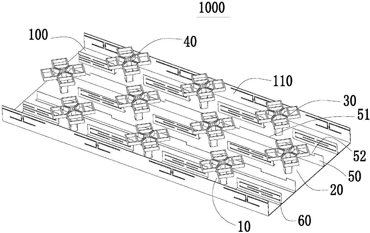
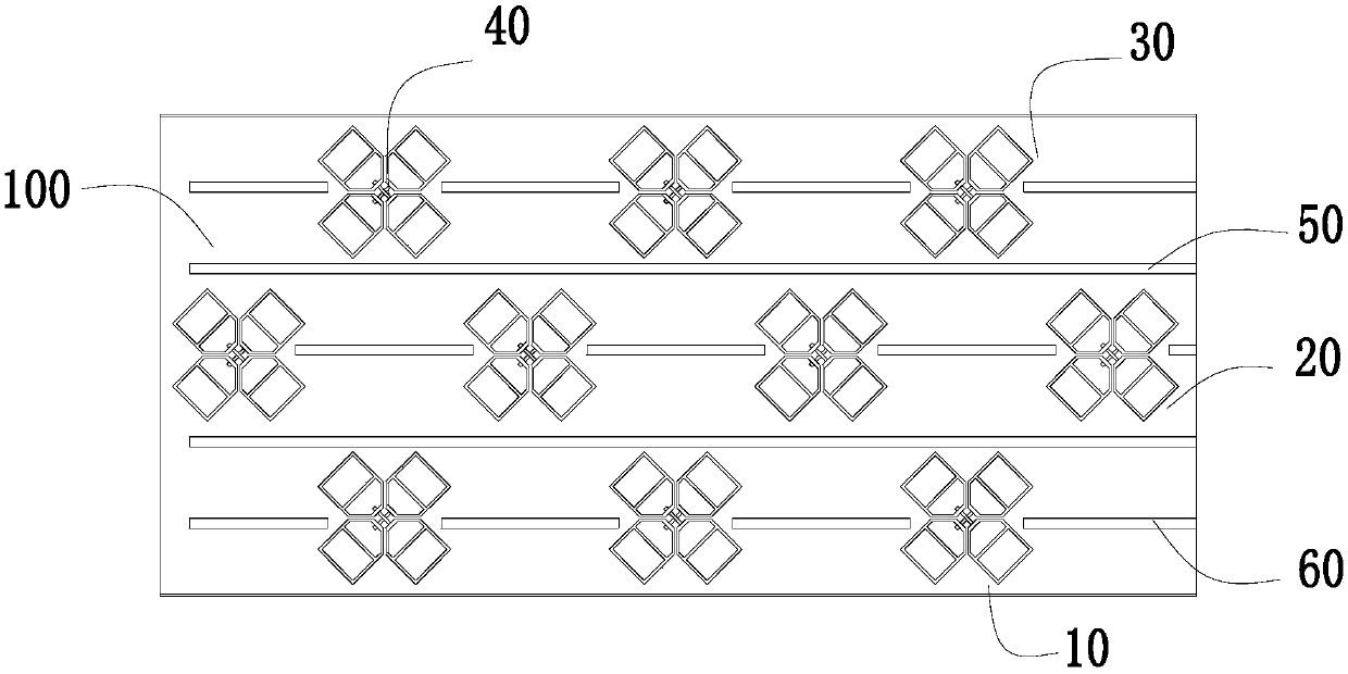
[0041] Aiming at the base station antenna whose working frequency range is 690MHz-960MHz, the present invention provides a multi-beam antenna, which solves the technical problem that miniaturization, high isolation, and high cross polarization cannot be simultaneously achieved in the prior art.

[0042] A multi-beam antenna of the present invention includes a reflector 100, a side plate 110 connected to the reflector 100, at least three rows of low-frequency arrays fixed on the reflector 100 and parallel to each other, and the Feed netwo...


PUM


Abstract

The invention provides a multi-beam antenna comprising a reflection plate, three or more columns of parallel low-frequency arrays fixed on the reflection plate, and frequency selection surfaces arranged on all axes of the low-frequency arrays or/and arranged at the two sides along the extending directions of the low-frequency arrays. Low-frequency radiating units of each two columns of low-frequency arrays are staggered. Therefore, on the premise that the miniaturization is guaranteed, the isolation and cross polarization between the low-frequency radiating units are improved and the performances of the antenna are enhanced; and objectives of simple structure and low cost are achieved.

Description

technical field [0001] The invention relates to the field of communication base station antennas, in particular to a multi-beam antenna based on a frequency band selection plane. Background technique [0002] The current explosive growth of mobile communication data traffic has put forward higher and higher requirements for system capacity. In order to cope with the ultra-high traffic and data volumes in dense urban areas, frequent sports events, holidays and other high-density scenarios, and to maximize the efficiency of site usage, one of the most effective methods is to use multi-beam antennas to integrate conventional 120 °Sectors are split again, without adding any spectrum resources and site resources, which improves the stability and carrying capacity of the operator's wireless network. As antennas are increasingly required to be miniaturized, in large-scale arrays such as 5G, the design concept of traditional phased arrays is to first independently design a broadban...

Claims


Application Information

Patent Timeline
Patent Type & Authority Applications(China)
IPC IPC(8): H01Q1/50H01Q1/52H01Q13/08H01Q15/00
CPCH01Q1/52H01Q1/50H01Q13/085H01Q15/0013
Inventor 王灿陈强王强
Owner COMBA TELECOM TECH (GUANGZHOU) CO LTD
Why Eureka
Try Eureka