
Salient pole synchronous motor rotor with integrated solid structure

A solid structure, synchronous motor technology, applied in synchronous machines, manufacturing motor generators, magnetic circuit shape/style/structure, etc., can solve problems such as high bolt stress, eddy current heating, rotor deformation, etc., and achieve high harmonic content less, improved safety and reliability, and strong overall carrying capacity

Active Publication Date: 2018-03-23
东方电气(德阳)电动机技术有限责任公司 +1
View PDF4 Cites 5 Cited by
  • Summary
  • Abstract
  • Description
  • Claims
  • Application Information

AI Technical Summary

Problems solved by technology

[0005] 1. The centrifugal force of the field winding and the pole shoe is borne by the bolts. The bolts have high stress, so high-strength bolts must be used. The quality and installation of the bolts are very high, and there is a risk of bolt breakage, and the loss caused by the breakage of the bolts will be very high. Big
[0006] 2. There are bolt holes on the outer surface of the pole shoe. When the motor is started, the eddy current will generate heat at the edges and corners. When the motor is started improperly, the pole shoe will heat up severely, causing the rotor to deform.
[0007] 3. The bolt holes on the outer surface of the pole piece cause the distortion of the magnetic field waveform and the increase of the voltage harmonic content
[0008] 4. Limited by the bolt strength limit, the diameter of the rotor cannot be larger, and the capacity of the motor is limited

Method used


Image

  • Salient pole synchronous motor rotor with integrated solid structure
  • Salient pole synchronous motor rotor with integrated solid structure
  • Salient pole synchronous motor rotor with integrated solid structure

Examples


Embodiment Construction

[0027] Below in conjunction with accompanying drawing, the present invention is described in detail.

[0028] In order to make the object, technical solution and advantages of the present invention clearer, the present invention will be further described in detail below in conjunction with the accompanying drawings and embodiments. It should be understood that the specific embodiments described here are only used to explain the present invention, not to limit the present invention.

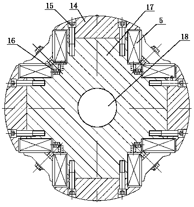
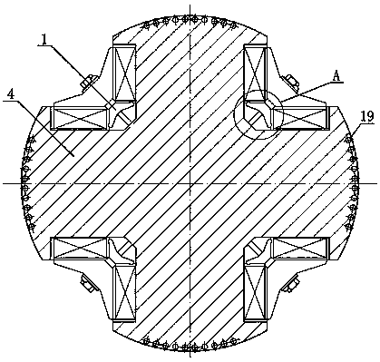
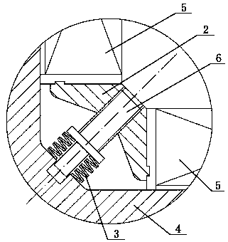
[0029] Such as figure 2 As shown, a salient pole synchronous motor rotor with integral solid structure includes pole piece 14, magnetic pole 17, rotating shaft 18 and field winding 5. The pole piece 14, magnetic pole 17 and rotating shaft 18 are excellent in magnetic and mechanical properties. The integral salient pole rotor structure 4 is integrally processed from forgings. The salient pole rotor structure 4 has a space reserved for setting the excitation winding 5. The excitation winding 5 is ...


PUM


Abstract

The invention discloses a salient pole synchronous motor rotor with an integrated solid structure. The rotor comprises a pole shoe, a magnetic pole, a rotation shaft and an exciting winding, wherein the pole shoe, the magnetic pole and the rotation shaft are machined into an integrated salient pole rotor structure by using a forge piece, the salient pole rotor structure is reserved with a space for arranging the exciting winding, the exciting winding is formed by directly winding on the rotor, and an elastic support device is arranged under the exciting winding.According to the salient pole synchronous motor rotor with the integrated solid structure provided by the invention, the pole shoe, the magnetic pole and the rotation shaft are machined into the integrated structure by using the forge piece with both excellent magnetic performance and mechanical property, without using a combining bolt, so that the whole carrying capacity is stronger, the rigidity is better, the capacity of themotor can become larger, and thus the rotor can bear larger centrifugal force, the stress of the rotor component is smaller under the effect of the same centrifugal force, and the security reliabilityis greatly improved; the surface of the pole shoe is a continuous curved surface without sharp corners and edges, so that the situation that local part heats seriously is eliminated, the magnetic field waveform is better, and the higher harmonic content becomes little.

Description

technical field [0001] The invention belongs to the technical field of salient-pole synchronous motors, in particular to a salient-pole synchronous motor rotor with an integral solid structure applied to high power and high speed. Background technique [0002] The salient pole synchronous motor is a type of rotating electrical machine, which has a stator and a rotor rotating around the central axis. The rotor is the carrier of mechanical energy transmission and the magnetic field of the motor. There is an excitation winding on the rotor that generates the magnetic field of the motor. The excitation winding is welded or bent by copper plates. The centrifugal force of the excitation winding is borne by other components on the rotor. In high-power (10-60MW), medium-high-speed (1500-1800r / min) salient pole synchronous motors, in order to solve the high stress problem caused by large size and high speed, integrally forged magnetic poles are often used instead of laminated magneti...

Claims


Application Information

Patent Timeline
Patent Type & Authority Applications(China)
IPC IPC(8): H02K19/00H02K1/24H02K1/28H02K15/00
CPCH02K1/24H02K1/28H02K15/00H02K19/00Y02T10/64
Inventor 徐勇仲伟林田德见孙小刚晏明吴成龙
Owner 东方电气(德阳)电动机技术有限责任公司
Learn More