Automatic testing method and system of camera device

A technology of automated testing and camera devices, applied in image communication, television, electrical components, etc., can solve problems such as high standard requirements, energy consumption, and inability to continue working, so as to avoid judgment bias, prolong service life, and reduce total work the effect of time

Inactive Publication Date: 2018-03-23
台州市吉吉知识产权运营有限公司
View PDF1 Cites 6 Cited by
  • Summary
  • Abstract
  • Description
  • Claims
  • Application Information

AI Technical Summary

Problems solved by technology

[0007] 4. If the power is cut off, it cannot continue to work;
However, in this invention, the detection of the network surveillance camera requires the addition of a passive infrared sensor, a voice detector and a control sub-module in the network surveillance camera, in order to complete the selective video monitoring of the target area and finally effectively reduce power consumption, so Not applicable to all surveillance cameras; in addition, the use of passive infrared sensors and voice detectors requires high standards for setting sample environments. As long as there is a slight change in the detected environment, the network surveillance camera will be triggered and powered on , resulting in excessive energy consumption

Method used


Image

  • Automatic testing method and system of camera device
  • Automatic testing method and system of camera device
  • Automatic testing method and system of camera device

Examples


Embodiment 1

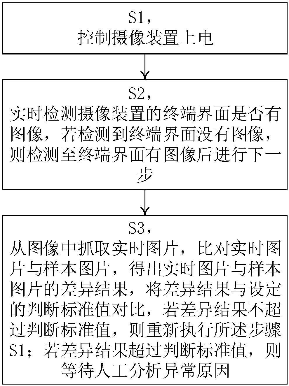
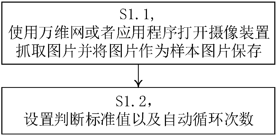
[0060] Such as Figure 1-3 , the automatic testing method of a kind of camera device of the present invention, comprises the following steps:

[0061] S1, controlling the camera device to be powered on.

[0062] S2, detecting in real time whether there is an image on the terminal interface of the camera device, and if it is detected that there is no image on the terminal interface, proceed to the next step after detecting that there is an image on the terminal interface.

[0063] S3, capture the real-time picture from the image, compare the real-time picture and the sample picture, obtain the difference result between the real-time picture and the sample picture, compare the difference result with the set judgment standard value, if the difference result does not exceed the judgment standard value, Then re-execute the step S1; if the difference result exceeds the judgment standard value, then wait for manual analysis of the cause of the abnormality.

[0064] The present invent...

Embodiment 2

[0088] Such as Figure 4-5 , the automatic test system of a kind of camera device of the present invention, comprises:

[0089] The power-on module controls the camera device to be powered on.

[0090] The power-on module also includes:

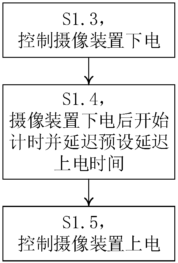
[0091] The power-off unit is configured to control the camera device to be powered off.

[0092] The delay unit is used for starting timing after the camera device is powered off and delaying the preset delayed power-on time.

[0093] The power-on unit is used to control the camera device to be powered on.

[0094] The detection module is used to detect in real time whether there is an image on the terminal interface. If it is detected that there is no image on the terminal interface, the next step is performed after detecting that there is an image on the terminal interface.

[0095] Whether there is an image in the terminal interface of the real-time detection camera device in the detection module is specifically:

[0096] Through the ...


PUM


Abstract

An automatic testing method and system for a camera device belong to the technical field of video monitoring. The method of the present invention comprises the following steps: S1, controlling the camera device to be powered on; S2, detecting in real time whether there is an image on the terminal interface of the camera device, if it is detected that there is no image on the terminal interface, then proceed to the next step after detecting that there is an image on the terminal interface; S3, Grab the real-time picture from the image, compare the real-time picture and the sample picture, get the difference result between the real-time picture and the sample picture, compare the difference result with the set judgment standard value, if the difference result does not exceed the judgment standard value, restart Execute the step S1; if the difference result exceeds the judgment standard value, wait for manual analysis of the cause of the abnormality. The invention uses an automatic device to control the entire testing process, saving labor costs; and automatically comparing the results to prevent judgment deviation caused by artificial visual fatigue.

Description

technical field [0001] The invention belongs to the technical field of video monitoring, in particular to an automatic test system for a camera device Background technique [0002] IP camera (IPC) is currently the mainstream security monitoring product form. Align the monitoring field of view of the IPC with the target area, and record the surveillance video of the target area, which is called arming; correspondingly, stop the video surveillance behavior of the target area, which is called disarming. [0003] In the prior art, network surveillance cameras have the following general characteristics: [0004] 1. Obtain images through imaging sensors; [0005] 2. Network transmission real-time stream; [0006] 3. Powered by DC or AC power supply; [0007] 4. If the power is cut off, it cannot continue to work; [0008] 5. The recording keeps running; [0009] 6. Fixed arming, that is, once installed, it is fixed in a certain place, and it is very difficult to move. [00...

Claims


Application Information

Patent Timeline
Patent Type & Authority Applications(China)
IPC IPC(8): H04N17/00
CPCH04N17/002
Inventor 梁勇
Owner 台州市吉吉知识产权运营有限公司
Why Eureka
Try Eureka