Integrated balance suspension cross beam assembly

A technology for balancing suspension and beam assembly, applied in the direction of suspension, cantilever mounted on the pivot, interconnection system, etc., can solve the problems of inability to have both the function of the air tank and uneven stress distribution, and achieve improved assembly. The effect of manufacturability, improving utilization, and improving torsion resistance

Active Publication Date: 2018-03-27
DONGFENG COMML VEHICLE CO LTD
View PDF11 Cites 4 Cited by
  • Summary
  • Abstract
  • Description
  • Claims
  • Application Information

AI Technical Summary

Problems solved by technology

[0005] The purpose of the present invention is to overcome the defects and problems existing in the prior art that the stress distribution is uneven under the torsion state and the function of the air storage cylinder cannot be combined, and to provide an integrated type with uniform stress distribution under the torsion state and the function of the air storage cylinder. Balance suspension beam assembly

Method used


Image

  • Integrated balance suspension cross beam assembly
  • Integrated balance suspension cross beam assembly
  • Integrated balance suspension cross beam assembly

Examples


Embodiment 1

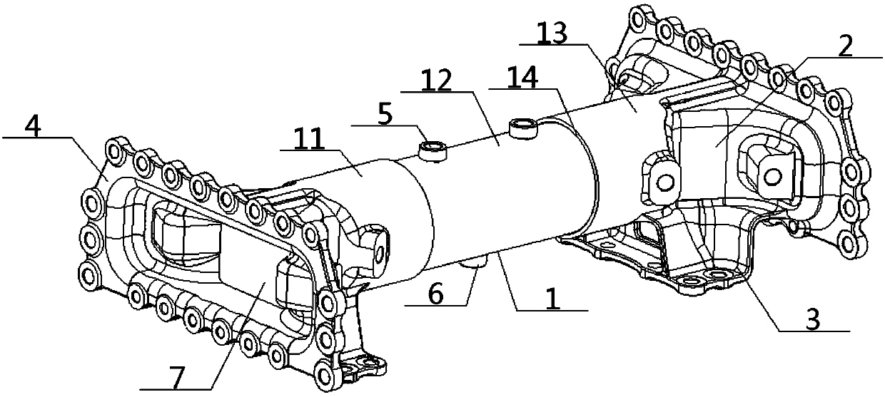
[0046] see Figure 1 to Figure 7 , an integrated balanced suspension crossbeam assembly, including a crossbeam body 1, a thrust rod connecting part 2, a large bracket connecting part 3 and a longitudinal beam connecting part 4, and the crossbeam body 1 is connected through the thrust rod connecting part 2 and the large bracket The part 3 and the longitudinal beam connecting part 4 are respectively connected with the thrust rod, the large bracket of the balance suspension and the longitudinal beam of the vehicle frame in one-to-one correspondence;

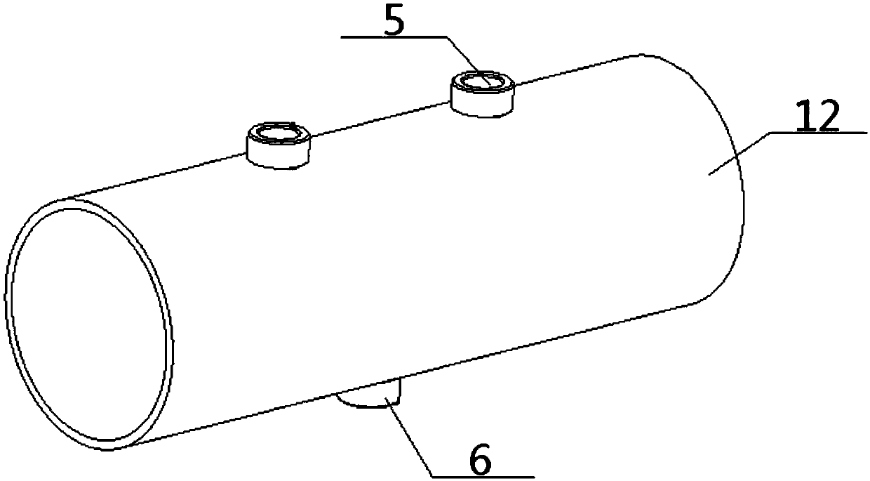
[0047] The beam body 1 is a hollow sealed cylindrical structure, and the top and bottom of the middle section of the beam body 1 are respectively provided with an inlet and outlet port 5 and a drain valve 6, and the inlet and outlet ports 5 are arranged higher than the drain valve 6, and Both ends of the beam body 1 are respectively connected with a thrust rod connecting portion 2 , a large bracket connecting portion 3 and a longitu...

Embodiment 2

[0049] Basic content is the same as embodiment 1, the difference is:

[0050] The beam body 1 includes a left cylindrical part 11, a middle cylindrical part 12 and a right cylindrical part 13 which are connected in sequence, and the diameters of the left cylindrical part 11 and the right cylindrical part 13 are larger than the diameter of the middle cylindrical part 12. , the two ends of the middle cylindrical part 12 are respectively located inside the inner end of the left cylindrical part 11 and the inner end of the right cylindrical part 13, and the outer walls of the two ends of the middle cylindrical part 12 are connected with the inner end of the left cylindrical part 11 and the right cylindrical part respectively. The inner walls of the inner ends of 13 are in contact, and the outer ends of the left cylindrical part 11 and the outer ends of the right cylindrical part 13 are respectively connected with a thrust rod connecting part 2, a large bracket connecting part 3 and...

Embodiment 3

[0053] Basic content is the same as embodiment 2, the difference is:

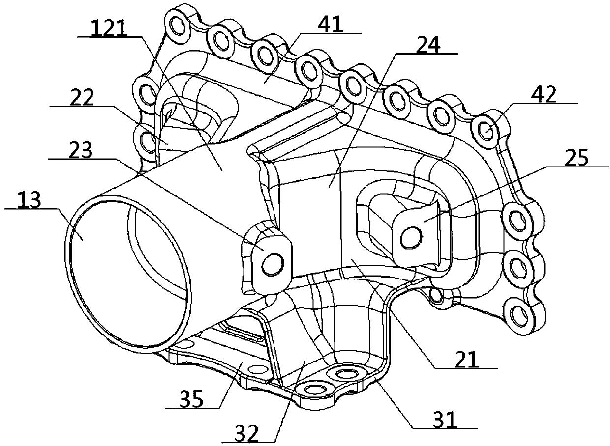
[0054] The longitudinal beam connection part 4 includes a connection base plate 41, a longitudinal beam connection hole 42 and a base plate inner cavity 43, the inner end of the connection base plate 41 is vertically connected with the two ends of the beam body 1, and the periphery of the connection base plate 41 is provided with a plurality of The longitudinal beam connection hole 42 connected with the frame longitudinal beam, the middle part of the outer end connecting the bottom plate 41 is provided with a bottom plate inner cavity 43, and the bottom plate inner cavity 43 is provided with a partition plate 7 for sealing and matching with the two ends of the cross beam body 1 . A pair of inwardly extending bosses 44 are arranged in the inner cavity 43 of the bottom plate, and a partition 7 is arranged between adjacent bosses 44 .


PUM


Abstract

Provided is an integrated balance suspension cross beam assembly. A cross beam body in the integrated balance suspension cross beam assembly has a hollow sealed cylindrical structure. An air inlet andoutlet, and a water drain valve are arranged at the top and bottom of the middle section of the cross beam body respectively. Both ends of the cross beam body are connected with thrust rod connectingportions, large bracket connecting portions and longitudinal beam connecting portions. The cross beam body may be left, middle and right cylindrical portions which are sequentially connected. The longitudinal beam connecting portions include connecting bottom plates, and longitudinal beam connecting holes and bottom plate inner chambers arranged above the connecting bottom plates. The thrust rodconnecting portions comprise front and rear thrust rod connecting branch portions which are symmetrically arranged front and back with a center axis of the cross beam body as a symmetry line. The large bracket connecting portions comprise bracket bottom plates, bracket bottom holes, and front and rear support plates. This design has uniform stress distribution under torsional conditions and can increase the torsional performance of the cross beam. The integrated balance suspension cross beam assembly has the function of acting as an air reservoir, the manufacturing and assembly efficiency canbe improved, and the overall weight is reduced so as to be conducive to the modular layout of chassis.

Description

technical field [0001] The invention relates to a balance suspension crossbeam assembly, which belongs to the field of the automobile industry, in particular to an integrated balance suspension crossbeam assembly, which is specifically suitable for increasing the torsional performance of the crossbeam and also has the function of an air storage tank. Background technique [0002] At present, the commonly used balance suspension beam assembly in the automotive field includes the beam body and the thrust rod bracket set on it. The large bracket is connected, the thrust rod support seat is connected with the belly of the beam body and the frame longitudinal beam by bolts, and the front and rear of the thrust rod support seat are provided with flat plates of hot-rolled steel plate material to strengthen the cross beam. [0003] The application publication number is CN105667235A, and the application publication date is June 15, 2016. The invention patent application discloses a b...

Claims


Application Information

Patent Timeline
Patent Type & Authority Applications(China)
IPC IPC(8): B60G21/055B60G7/00B60T17/06
CPCB60T17/06B60G7/008B60G21/055B60G2204/8302B60G2206/011B60G2204/148
Inventor 蒋光辉刘尧王金胜谢浩张嘉翼赵翔
Owner DONGFENG COMML VEHICLE CO LTD
Why Eureka
Try Eureka