Bridge anti-collision device

A technology of anti-collision devices and bridges, which is applied in the direction of bridges, bridge parts, bridge materials, etc., and can solve problems such as inability to lower, poor flexibility, small boats capsized, etc.

Active Publication Date: 2018-03-27
ZHENGZHOU UNIVERSITY OF AERONAUTICS
View PDF6 Cites 9 Cited by
  • Summary
  • Abstract
  • Description
  • Claims
  • Application Information

AI Technical Summary

Problems solved by technology

[0003] Most of the traditional bridge anti-collision devices are used directly on the bridge pier, let the ship hit the device and use the springs on the device to bounce the ship back to act as a fender, which can effectively protect the pier from collisions for small ships. The impact force between the small ship and the anti-collision device will be very large, which will cause a large sliding friction force between the small ship and the anti-collision device, so that the speed of the ship will decrease rapidly, resulting in the cargo on the ship under inertia. Under the action, it capsizes into the river and sea, causing losses, and it is easy to cause small ships to capsize
Although this kind of bridge anti-collision device has played a protective role for the bridge pier, it has caused certain life-threatening dangers to the fishermen and cargo personnel on board, and the loss caused by the cargo capsizing into the river and sea under the action of inertia is irreparable
Moreover, the bridge anti-collision device in the prior art cannot adjust the position of the free adjustment device according to the rise and fall of the water level, and the flexibility in use is poor.

Method used


Image

  • Bridge anti-collision device
  • Bridge anti-collision device

Examples


Embodiment

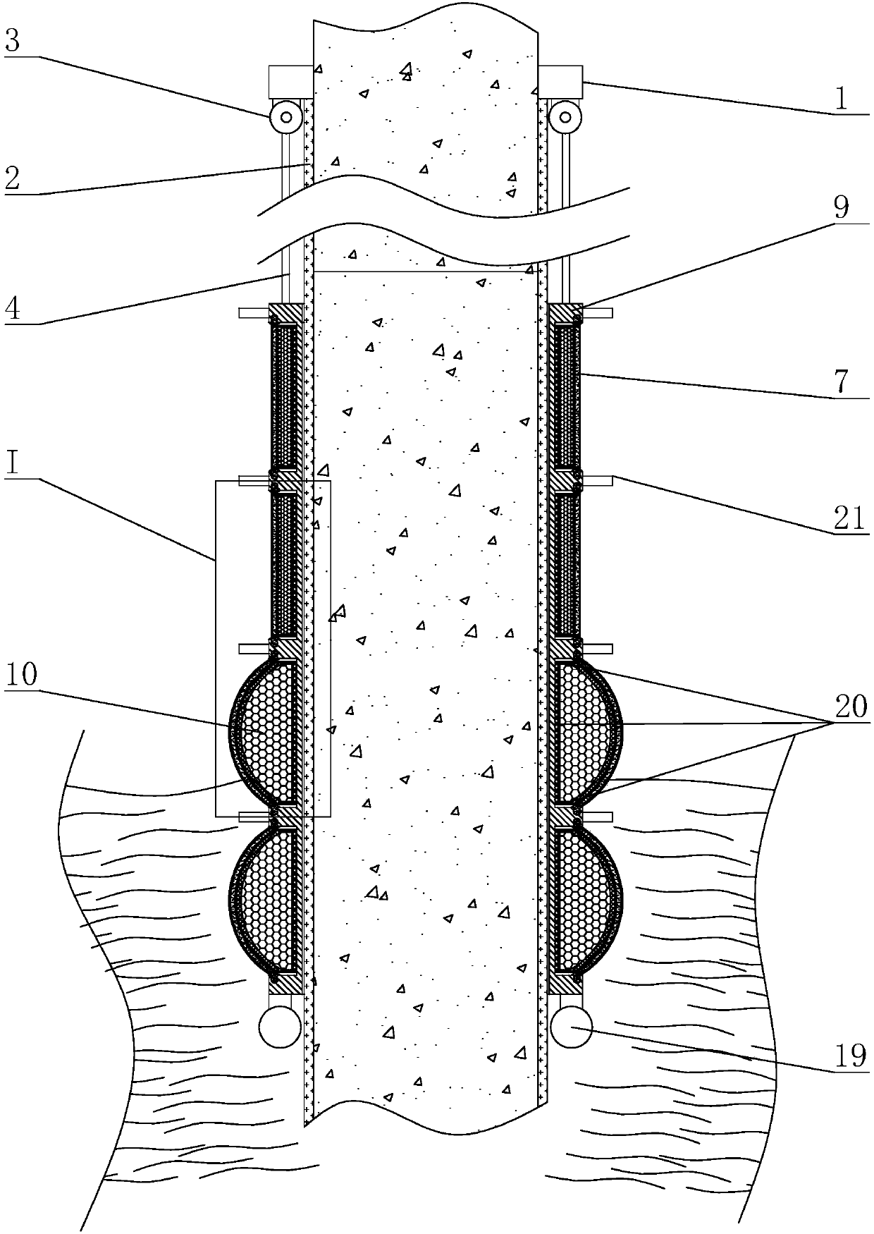
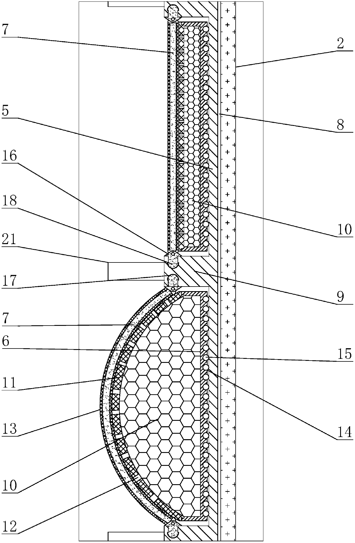
[0034] The present invention is a bridge anti-collision device, the main structure includes a position adjustment mechanism and an anti-collision device assembly, the position adjustment mechanism includes a load-bearing frame 1, a vertical guide rail 2, a coil spring box 3 and a pull rope 4, the The anti-collision device assembly includes a ring-shaped sliding bracket 5, a ring-shaped box body 6 and a glue stick shaft 7. The load-bearing frame 1 is fixedly arranged on the pier, and the vertical guide rail 2 is vertically arranged along the surface of the pier. The circular array of guide rails 2 is arranged on the surface of the pier. The coil spring box 3 is provided with a coil spring, one end of the stay rope 4 is connected to the inside of the coil spring box 3, and the other end of the stay rope 4 is connected to the top of the ring-shaped sliding bracket 5. A vertical chute 8 slidingly connected to the vertical guide rail 2 is provided, and a plurality of annular flange...


PUM


Abstract

The invention discloses a bridge anti-collision device, and mainly relates to the technical field of bridge design. The bridge anti-collision device comprises a position adjusting mechanism and an anti-collision device assembly. The position adjusting mechanism comprises a bearing frame, a vertical guide rail, a coil spring box and a pull rope. The anti-collision assembly comprises an annular sliding support, an annular box and rubber bar shafts. The annular sliding support is provided with a vertical sliding groove in sliding connection with the vertical guide rail, annular flanges are arranged on the annular sliding support, and the annular box and the rubber bar shafts are arranged between the adjacent annular flanges. Water swelling rubber is arranged in the annular box, water-perviousholes are formed in the face of the soft rubber, and the rubber bar shafts are arranged between the adjacent annular flanges and sleeved with rubber pipes. The bridge anti-collision device has the beneficial effect that the position of the device can be freely adjusted according to rising and dropping of the water level. After a ship collides with the bridge anti-collision device, the course canbe changed smoothly, the speed of the ship is not greatly influenced, and the ship can smoothly pass through the bridge anti-collision device.

Description

technical field [0001] The invention relates to the technical field of bridge design, in particular to a bridge anti-collision device. Background technique [0002] At present, the construction of cross-river and sea-crossing bridge projects is being carried out rapidly, and my country has carried out the construction of an arterial highway network running from north to south and from east to west. The construction of large bridges can relieve traffic pressure and promote land traffic. But for ships on water, bridges are artificial obstacles. Due to many factors such as the natural environment, navigation environment, ship conditions, ship operators and managers, vicious accidents of ships colliding with bridges occur from time to time. In order to ensure the safe operation of bridges, various bridge anti-collision devices have appeared. [0003] Most of the traditional bridge anti-collision devices are used directly on the bridge pier, let the ship hit the device and use ...

Claims


Application Information

Patent Timeline
Patent Type & Authority Applications(China)
IPC IPC(8): E02B3/26E01D19/00E01D101/30
CPCE01D19/00E01D2101/30E02B3/26Y02A30/30
Inventor 李亮李广慧丁雅豪张攀
Owner ZHENGZHOU UNIVERSITY OF AERONAUTICS
Why Eureka
Try Eureka