
dual drive compressor

A compressor and dual-drive technology, applied in the field of compressors, can solve the problems of low compressor operating speed, long switching time, small transmission ratio, etc., and achieve the effects of reducing impact, improving user experience, and improving smooth rotation

Active Publication Date: 2019-09-13
BYD CO LTD
View PDF12 Cites 0 Cited by
  • Summary
  • Abstract
  • Description
  • Claims
  • Application Information

AI Technical Summary

Problems solved by technology

[0005] First of all, due to the limitation of the traditional structure of the electromagnetic clutch, the transmission ratio between the compressor pulley and the driving wheel of the engine is small, that is, the displacement of the compressor is required to be increased. In order to make the compressor with a large displacement work normally, the maximum output torque of the driving motor needs to be increased. , the increased torque requires that the withstand voltage and current withstand capabilities of the electrical components of the controller must be improved at the same time;
[0006] Secondly, due to the small transmission ratio, the compressor has low operating speed and low efficiency, and cannot take advantage of the high-speed and high-efficiency advantages of the scroll compressor;
[0007] Furthermore, the clutch drive and the motor drive will experience vibration during the mode switching process. The sudden load change has high requirements on the performance of the clutch or the motor. Its structural form cannot be seamlessly connected, and the switching time is long, which affects the user experience;
[0008] Finally, no improvements have been made to the electrical control of the compressor

Method used


Image

  • dual drive compressor
  • dual drive compressor
  • dual drive compressor

Examples


Embodiment Construction

[0066] Specific embodiments of the present disclosure will be described in detail below in conjunction with the accompanying drawings. It should be understood that the specific embodiments described here are only used to illustrate and explain the present disclosure, and are not intended to limit the present disclosure.

[0067] In this disclosure, for the convenience of description, the orientation words used such as "front and rear" are defined by the inventor according to a specific structure, for example, as far as the crankshaft is concerned, in its axial direction In terms of direction, the end connected to the clutch assembly is the front, and the opposite end is the rear; "inner and outer" generally refer to the contours of the corresponding parts.

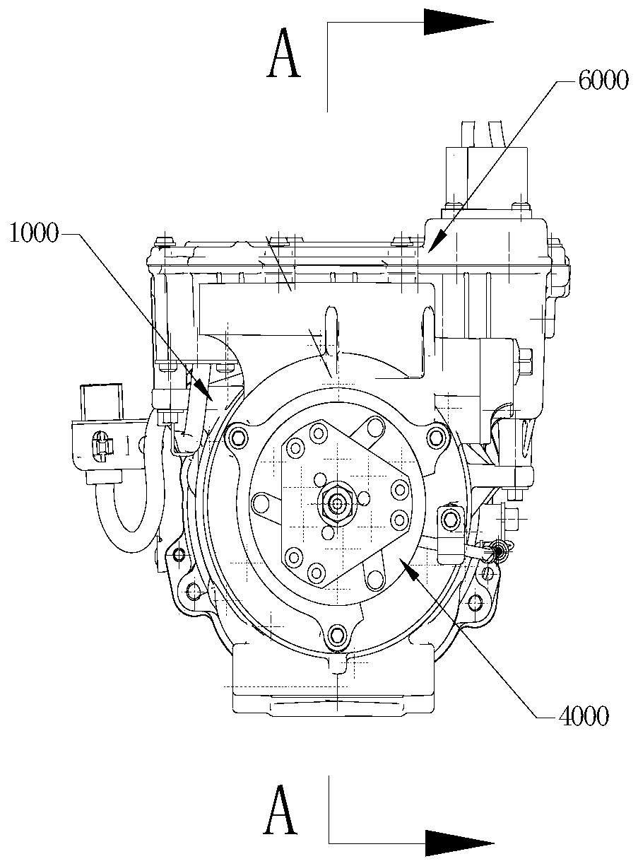
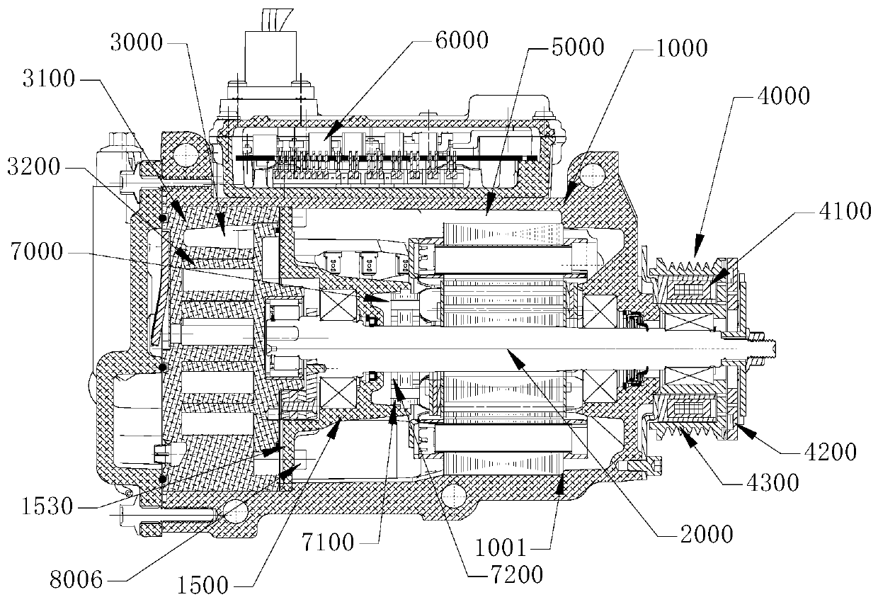
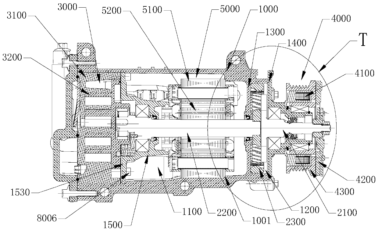
[0068] The present disclosure provides a dual-drive compressor, combined with figure 1 and figure 2 Firstly, the basic structure and working principle of the dual-drive compressor are introduced.

[0069] Such as figu...


PUM


Abstract

A dual-drive compressor, comprising: a casing assembly (1000); a scroll assembly (3000), a crankshaft (2000) and a motor assembly (5000) which are located inside the casing assembly (1000); an electrical control assembly (6000) mounted outside the casing assembly (1000); and a clutch assembly (4000) connected to the crankshaft (2000), and further comprising a rotary transformer (7000) mounted on the crankshaft. The rotary transformer (7000) is electrically connected to the electrical control assembly (6000). The compressor can be in a seamless connection during power switching, avoiding loss of air conditioning function and improving user experience.

Description

technical field [0001] The present disclosure relates to compressors, and in particular, to a dual drive compressor. Background technique [0002] With the development of the new energy automobile industry, the application of hybrid electric vehicles is becoming more and more extensive. In the use of hybrid electric vehicles, the battery power of the car is consumed in pure electric driving mode. When the vehicle feeds power, the remaining power cannot be provided to Electric air-conditioning compressor, the air-conditioning system cannot work normally, and the comfort of the car environment deteriorates. In addition, the lubrication effect of traditional fuel oil compressors is poor, and the oil circuit can only rely on the large circulation of the system. A small amount of refrigerated oil carried by the refrigerant returns to the compressor in the form of gas-liquid two-phase, and the durability of the operating mechanism is not good. [0003] Chinese invention patent ap...

Claims


Application Information

Patent Timeline
Patent Type & Authority Patents(China)
IPC IPC(8): F04C23/02F04C18/02F04C29/04F04C29/00
Inventor 陈雪峰杨应葵易夏辉任光远
Owner BYD CO LTD
Learn More