Method for guiding crack in edge portion of donor substrate by using inclined laser beam

A donor and substrate technology, applied in laser welding equipment, semiconductor devices, fine working devices, etc., can solve the problem of edge effects

Active Publication Date: 2018-03-27
SILTECTRA
View PDF4 Cites 7 Cited by
  • Summary
  • Abstract
  • Description
  • Claims
  • Application Information

AI Technical Summary

Problems solved by technology

[0007] It has been found that although it is possible to produce a modification in a solid at a distance from the edge of the solid with the aid of a laser beam, this is not readily possible in the region of the edge of the solid due to edge effects.

Method used


Image

  • Method for guiding crack in edge portion of donor substrate by using inclined laser beam
  • Method for guiding crack in edge portion of donor substrate by using inclined laser beam
  • Method for guiding crack in edge portion of donor substrate by using inclined laser beam

Examples


Embodiment Construction

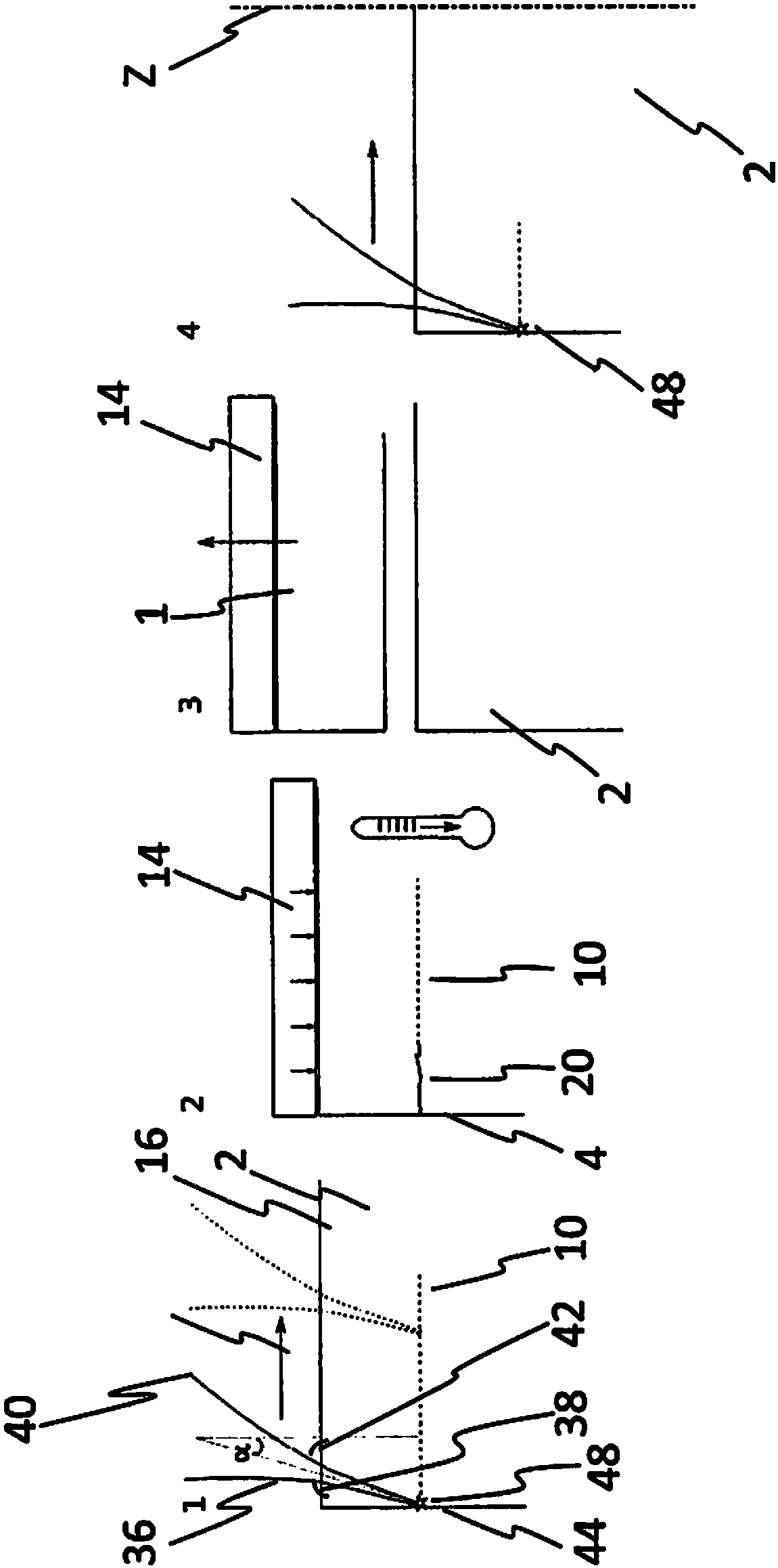
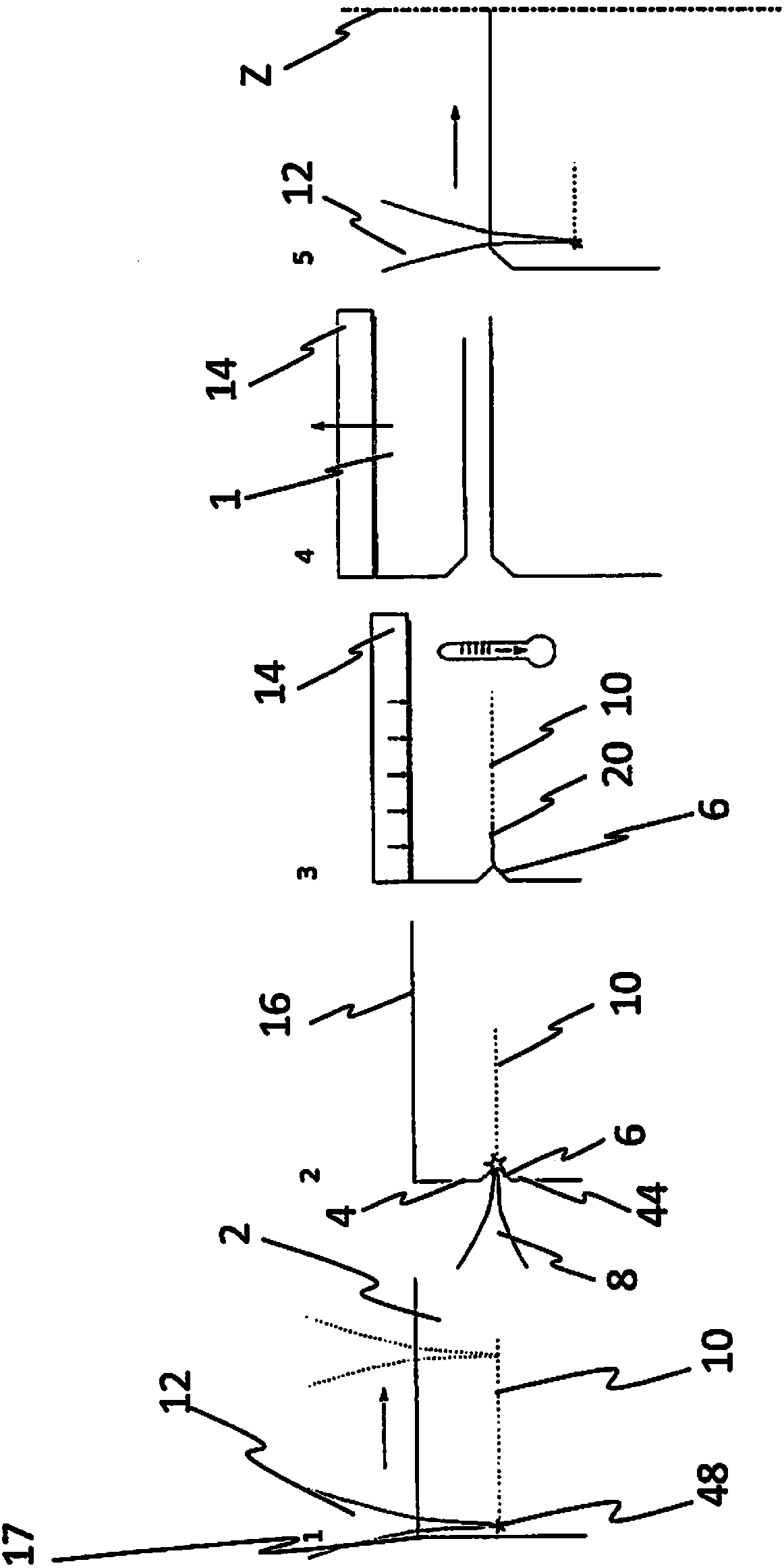
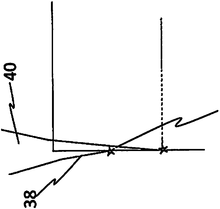
[0048] figure 1 4 views are shown. exist figure 1 In a first view of , a donor substrate 2 is shown, which is loaded with a laser beam 12 . The laser beam 12 is generally inclined relative to the surface 16 via which the laser beam enters the donor substrate 2 such that the inclination is at an angle different from 90°. Preferably, a first portion 36 of the laser beam 12 is aligned at a first angle 38 relative to the surface 16 and a further portion 40 of the laser beam 12 is aligned at a second angle 42 relative to the surface 16 . The laser beam sections 36 and 40 are preferably always inclined at the same angle relative to the surface 16, via which the laser beam sections 36, 40 enter the donor, for the overall generation of the modification 12 for separating a specific solid layer 1. Substrate 2. In addition to being able to Figure 4 It can be seen from the first view of FIG. 2 that the focal point 48 can be directed as far as the edge 44 or directly to the edge 44 i...


PUM


Abstract

The invention relates to a method for cutting solids wafers (1) off a donor substrate (2). The method comprises the following steps of: providing the donor substrate (2); producing at least one modification (10) in the interior of the donor substrate (2) by means of at least one laser beam (12), wherein the laser beam (12) penetrates the donor substrate (2) via a flat surface (16) of the donor substrate (2). The laser beam (12) is inclined with respect to the flat surface (16) of the donor substrate (2) such that it penetrates the donor substrate at an angle of not equal to 0 degree or 180 degrees relative to the longitudinal axis of the donor substrate. The laser beam (12) is focused in order to produce the modification (10) in the donor substrate (2) and the solids wafer (1) detaches itself from the donor substrate (2) as a result of the modifications (10) produced. Or a stress-inducing layer (14) is produced in or arranged on the flat surface (16) of the donor substrate (2) and mechanical stress is produced in the donor substrate (2) by exposing the stress-inducing layer (14) to heat. The mechanical stress produces a crack (20) for separating a solids layer (1), and the crack propagates along the modifications (10).

Description

technical field [0001] The invention according to claim 1 relates to a method for separating a solid sheet from a donor substrate. Background technique [0002] In many technical fields such as microelectronics or photovoltaics, materials such as silicon, germanium or sapphire are often used in the form of sheets and plates (so-called wafers). Conventionally, wafers of this type are currently produced by sawing from an ingot, wherein a relatively large loss of material occurs (“kerf loss”). Since the starting materials used are generally very expensive, there is a strong desire to produce such wafers more efficiently and cost-effectively with less material outlay. [0003] For example, with methods commonly used today, almost 50% of the material used is lost as "kerf loss" only in the production of silicon wafers for solar cells. On a worldwide basis, this corresponds to annual losses of more than 2 billion euros. Since the cost of the wafer accounts for the largest share...

Claims


Application Information

Patent Timeline
Patent Type & Authority Applications(China)
IPC IPC(8): B23K26/00B28D1/00B28D1/22B28D5/00C03B33/02C03B33/09C03B33/095H01L21/268H01L21/304B23K26/53B23K101/40
CPCB23K26/0006B28D1/221B28D5/0005B23K26/53B23K2101/40C03B33/0222C03B33/091H01L21/02005H01L21/268H01L21/304B81C1/00634H01L21/76251H01L31/1804H01L31/1896
Inventor 马尔科·斯沃博达克里斯蒂安·拜尔弗朗茨·席林扬·黎克特
Owner SILTECTRA
Why Eureka
Try Eureka