Scanning probe microscope

A probe microscope and scanning type technology, applied in the field of scanning probe microscope, can solve the problems of difficult to intuitively understand the adjustment of the position of the mark, and achieve the effect of simple optical axis adjustment, reducing deviation and reducing burden

Active Publication Date: 2018-03-27
SHIMADZU SEISAKUSHO CO LTD
View PDF14 Cites 1 Cited by
  • Summary
  • Abstract
  • Description
  • Claims
  • Application Information

AI Technical Summary

Problems solved by technology

Of course, the optical axis can be adjusted by such a method, but it may be difficult for an operator accustomed to the conventional optical axis adjustment work to intuitively understand the adjustment of the position using the marker.

Method used


Image

  • Scanning probe microscope
  • Scanning probe microscope
  • Scanning probe microscope

Examples


Embodiment Construction

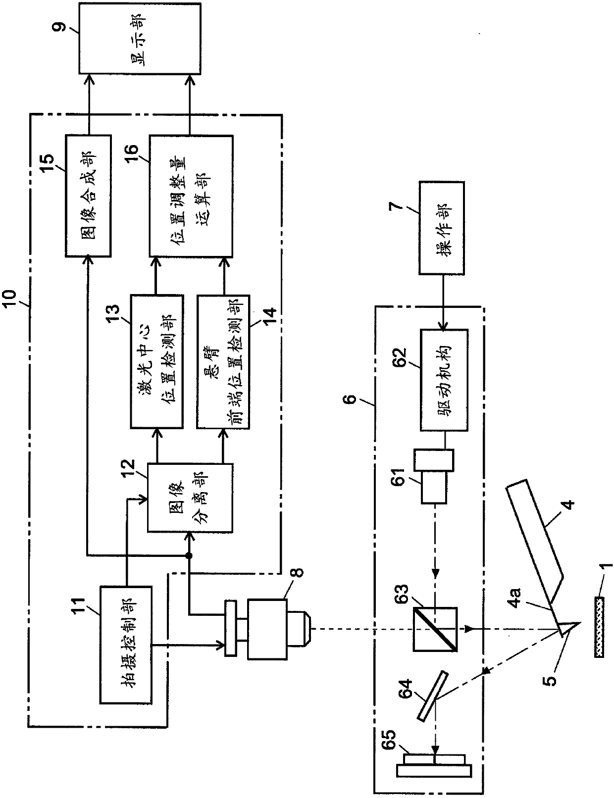
[0045] Hereinafter, a scanning probe microscope, which is an embodiment of the present invention, will be described with reference to the drawings. figure 1 It is a configuration diagram of main parts of the scanning probe microscope of this embodiment. right with Figure 7 The same components as those shown in the conventional scanning probe microscope are assigned the same reference numerals, and detailed descriptions thereof are omitted.

[0046] The scanning probe microscope of the present embodiment includes an optical axis adjustment control and processing unit 10 that controls the camera 8 and controls the camera 8 as a component that is not included in the conventional device. A function for processing image data captured by the camera 8 . The optical axis adjustment control and processing unit 10 includes an imaging control unit 11, an image separation unit 12, a laser center position detection unit 13, a cantilever front end position detection unit 14, an image syn...


PUM


Abstract

For each single picture, an imaging control unit (11) controls a video camera (8) so as to capture an image while switching between a first imaging condition suitable for capturing an image of a laserlight spot and a second imaging condition suitable for capturing an image of a cantilever. A picture synthesis unit (15) creates a picture in which a laser light spot image and a cantilever image clearly appear in each of two consecutive pictures, and displays the picture in a display unit (9). A laser light center position detection unit (13), a cantilever tip position detection unit (14), and aposition adjustment amount computation unit (16) calculate a position adjustment amount for adjusting an optical axis from the laser light center position and the cantilever tip position obtained byimage processing from each of the two consecutive pictures, and the calculated numerical value is also displayed in the display unit (9). An operator operates an operating unit (7) while viewing the pictures and the adjustment amount, and executes an optical axis adjustment. Optical axis adjustment can thereby be easily and reliably performed on the basis of a real observation picture not adequately viewable by normal imaging.

Description

technical field [0001] The present invention relates to a scanning probe microscope, and more specifically, to a scanning probe microscope including a displacement detection unit that optically detects the mechanical displacement of a cantilever on which a probe is placed. Background technique [0002] As a device for observing the surface of metals, semiconductors, ceramics, synthetic resins, etc. or measuring surface roughness, there is a scanning probe microscope (SPM: Scanning Probe) represented by an atomic force microscope (AFM: Atomic Force Microscope). Microscope), the atomic force microscope (AFM: Atomic Force Microscope) measures the atomic force acting between the probe (probe) and the surface of the sample. Although various measurement modes can be used in the atomic force microscope, recently, a method called non-contact mode or dynamic mode is used more frequently. The interaction between the probe and the sample surface is converted into a change in the ampli...

Claims


Application Information

Patent Timeline
IPC IPC(8): G01Q20/02
CPCG01Q20/02G01Q30/04G03F7/2049G06F3/147
Inventor 永井正道
Owner SHIMADZU SEISAKUSHO CO LTD
Why Eureka
Try Eureka